26. February 2024 © Copyright 2024, PROCEQ SA 49
5.17 Line Scan
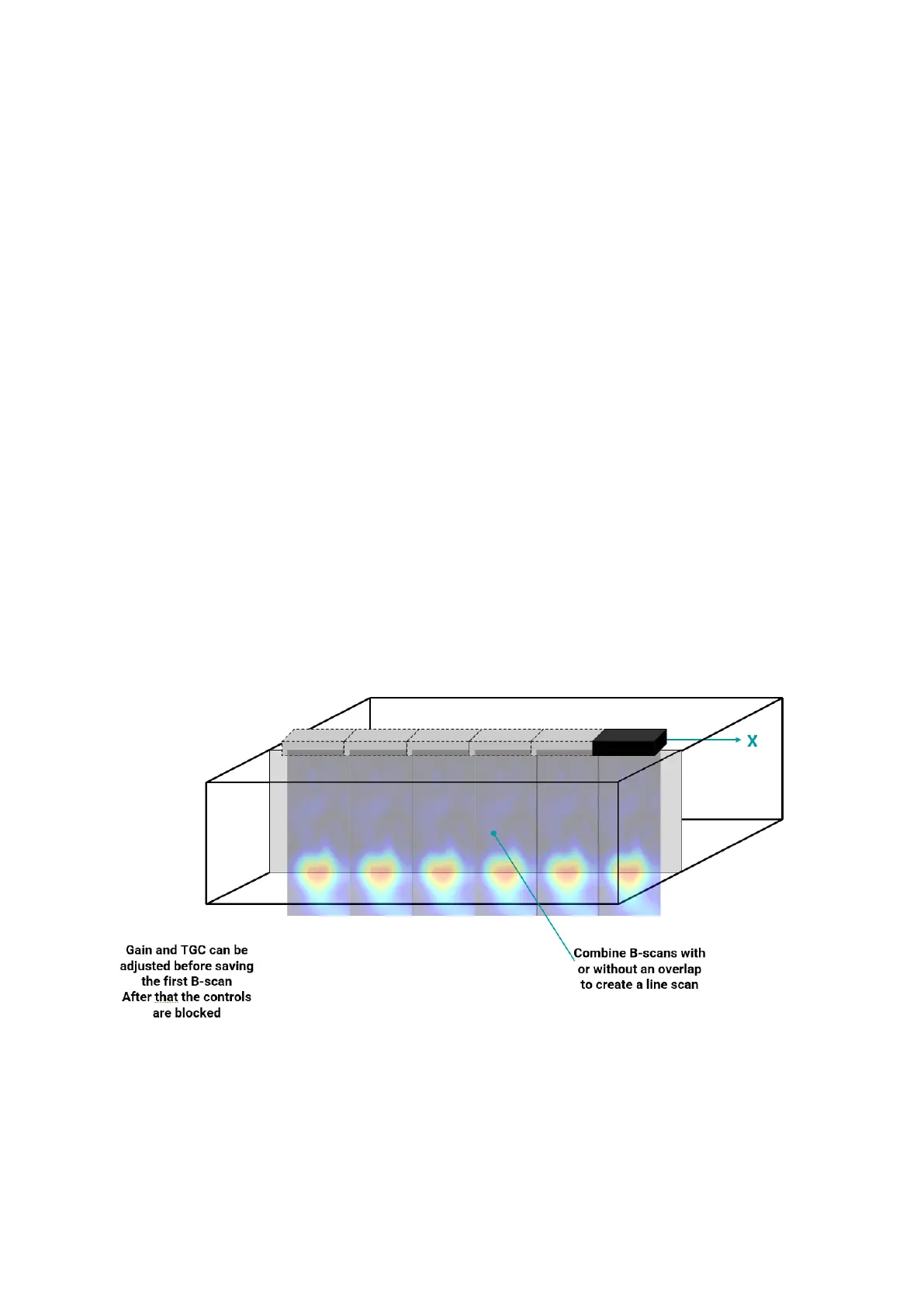
A Line Scan can be created by stitching individual B-scans together to make a larger image.
A scan is always carried out from left to right.
Scan parallel to the long axis of the sensor. This mode will combine each individual B-scan
with or without an overlap to create a line scan.
Please note that the analog gain and TGC can only be adjusted before saving the first B-scan.
After that, these controls will be blocked.
However, digital gain and TGC can be adjusted at any time and after the scan has been
finished.
Zero Overlap means that the transducer is moved by a complete transducer length to create
the next B-scan.
Due to the edge effects caused by the SAFT algorithm, an image created with zero overlap
can be disjointed at the borders. For this reason, it is often better to use an overlap.
For best results and ease of alignment when carrying out the scan it is best to set the overlap
as a whole number of channels (each channel overlap is equal to 3cm).
When carrying out a typical application like trying to determine the extent of delamination on a
large structure, it may be preferable to leave a gap between B-scans to reduce the effort.
Figure 50: Line Scan Sketch.
Unless AI positioning is used (by using the measuring tape), it will be necessary to set the X
spacing. This is equivalent to how far you want to move the sensor between snapshots.
The default spacing is x = 21cm, which is equal to the distance between the outer transducers.