Matrix 6/816 Installation Manual
RINS546-10 Page 5
2. WIRING DIAGRAMS
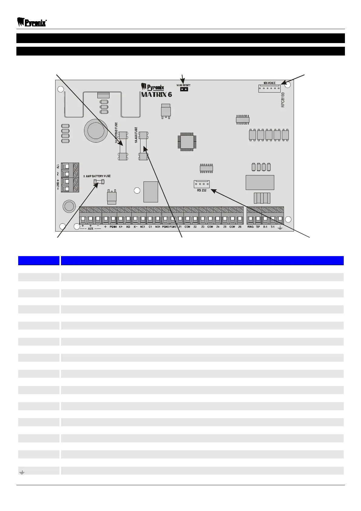
2.1 Matrix 6 PCB
Connector for
MX-VOICE module
RS232 port for direct
connection to PC
Fuse 1A of RKP
supply output “K+”
Fuse 5A of
battery output
Fuse 1A of auxiliary
supply output “+AUX”
Panel configuration
reset link
Terminal Designation
17V ~ 17V AC supply input for transformer connection
+BAT- 12V DC supply input for connection to the battery
+AUX- Auxiliary supply output for detectors. Protected by a 1 Amp “AUX FUSE”
+ Positive supply to the bell sounder. Protected by a 1 Amp “AUX FUSE”
PGM4 PGM4 transistor output
K+, K– RKP supply output. Protected by a 1 Amp “KEYPAD FUSE”
KD RKP data bus
NC1 PGM1 relay output. Normally closed contact
С1 PGM1 relay output. Common contact
NO1 PGM1 relay output. Normally open contact
PGM2 PGM2 transistor output
PGM3 PGM3 transistor output
Z1 Zone 1 input
COM Common input for zones (0V)
Z2 Zone 2 input
Z3 Zone 3 input
COM Common input for zones (0V)
Z4 Zone 4 input
Z5 Zone 5 input
COM Common input for zones (0V)
Z6 Zone 6 input
RING Communicator input for connection to Analogue PSTN telephone line
TIP Communicator input for connection to Analogue PSTN telephone line
R-1 Telephone line output for connection to the other telephone equipment
T-1 Telephone line output for connection to the other telephone equipment
Earth terminal for lightning protection
 Loading...