! Matrix 832 / 832+ / 424
RINS428-5 Page 99
10.2 System Faults & Maintenance
MEANING
Programmable Options Explanation
NOTE: See system faults in the memory log table in Section 10.1 for descriptions of possible faults,
which may occur.
10.2.1 NVM Reset to Factory Default
The system may be programmed for two different ways of reset to factory default.
Link Only Reset - If the engineer has configured this method in System Options (see Section 7.5), resetting
the system back to factory settings is achieved by powering up the system with the NVM reset pins shorted
together.
Proceed as follows:
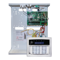
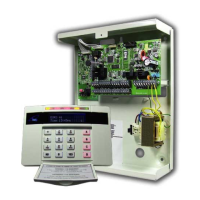
1. Locate the NVM reset pins on the PCB, using the link pin provided connect the two pins together.
2. Power down the system (AC and DC supply).
3. Restore power. Three different tones will be heard on power up and a further three same tone beeps after
approximately 25 seconds.
4. Remove the pin when the panel is operating correctly.
Engineer Code and Link Power Up Reset - If the engineer has configured this method in System Options
(see Section 7.5), follow the procedure bellow:
1. From Engineer Mode locate the NVM reset pins on the PCB without powering down the panel
2. Using the link pin provided connect the two pins together
3. Enter the procedure from the keypad as indicated bellow in Section 9.2.1.
4. Remove the pin when the panel is operating correctly.
This option is used for factory reset when higher security application is required.
10.2.2 Programmable Outputs Test
This option allows the engineer to test the operation of the programmable outputs from Engineer Mode.
10.2.3 Walk Test
This function allows the engineer to walk test the system from Engineer Mode.
10.2.4 Scan for Devices on the Bus
This option must be run every time something is added to the bus. Upon completion of the installation or
addition or removal of devices on the KD line the panel must be aware of the changes, otherwise a system
fault may occur. This function is automatic and only requires starting by the installer.
The keypad, which is being used for Engineer Mode will show the current device being checked for, all
devices in numeric order, upon finding a device the panel will reset and send the operational information
required. Additionally the found device will be entered into the log for later reference, please refer to the log
information table.
Log Information Table Related to the Event Table (Remote Devices on Bus ID) Device Types/Ids
LH Digit – (Type) RH Digit – (ID) Device Type
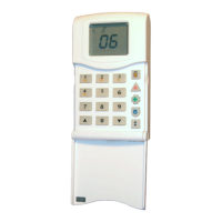
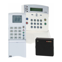
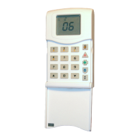
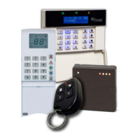
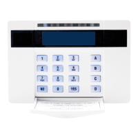
0 1-4 LCD Keypad
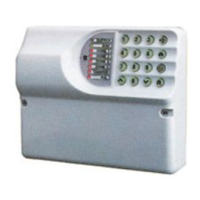
1 1-4 LED/ICON Keypad
2 1-4 Proximity card reader
3 1-4 4-Way output expander
4 1-4 8-Way output expander
5 1-4 4-Way Zone expander
6 1-4 8-Way Zone expander
 Loading...
