Matrix 832 / 832+ / 424
Page 122 RINS428-5
Diagrams
This section contains a number of wiring diagrams showing you how to connect to the Matrix alarm panel and
the various bus devices. These drawings are intended to help speed up your installation time as well as
provide you with real world connection solutions and ideas.
The diagrams listed in this section include:
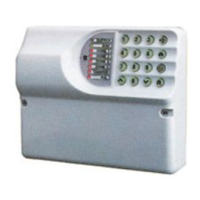
• Matrix 832, 882+ & 424
• Matrix Voice module
• Battery monitor module
• Zone expanders
• Output expanders (transistor and relay types)
• Keypads
• Proximity reader
• Digital communicator
• Belle
• Decibel
• Twin alert
• Vocaliser
• Buzzer, LED and siren
• Fire detectors
• Zones:
• Zone Doubling
• Double End Of Line
• Normally Closed
GLOBAL TAMPER CONNECTION
Note: The global tamper connections are very important
The global tamper connections on the 832 and 832+ control panel are GT and AUX- ,
Devices should be connected between these two terminals to create a global tamper
loop.
The 424 control panel does not have the GT terminal connection, so AUX- and a zone
terminal should be used to create the tamper loop.