18 19
485A
485B
GND
COM
NO
GND
DC +12V
IN
VGAHDMI E-SATA
VIDEO IN
CVBS
OUT
AUDIO
OUT
1 2 3 4 5 6 7 8
RJ45 USB
1 2 3 4 5 6 7 8
ALM IN
21 3 4 6 7 85
ON
OFF
AUDIO IN
1 3
5 76 98 11 1310 12 14
42
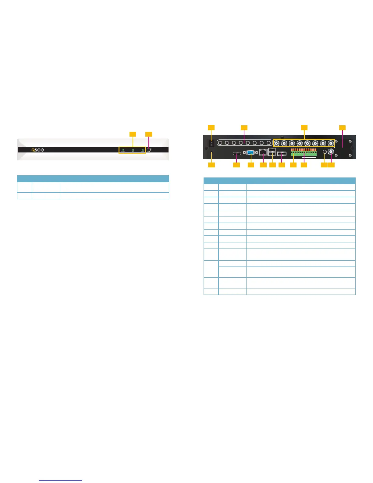
Item #
Connector Description
1 Power Switch Turn the DVR off after shutting it down from the Menu.
2 AUDIO IN 8 RCA connectors for microphones
3 VIDEO IN 8 BNC video inputs for connecting analog video cameras
4 FAN Cooling fan exhaust port. This should not be blocked.
5 DC 12V DC 12V/3A Power Connection
6 HDMI To connect to a HD display
7 VGA OUTPUT To connect to VGA monitor
8 NETWORK For connecting Ethernet cable
9 USB 2 USB ports for a mouse and external USB drive
10 E-SATA To connect to an external SATA drive.
11 RS485
RS485 for connecting PTZ
485A is “Positive” and 485B is “Negative”
12
ALARM INPUT 8 I/O Alarm input
ALARM
OUTPUT
I/O Output for alarm
13
AUDIO
OUTPUT
RCA connector for output to amplified speaker
14 VIDEO OUT Video output for connecting to TV (BNC)
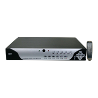
Item # Name/ Symbol Description
1 LED
INDICATORS
Shows status of hard drive, network, and whether the DVR is
currently recording.
2 IR SENSOR IR Receiver for remote control.
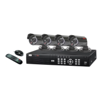
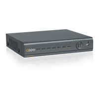
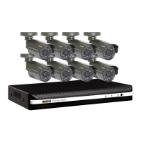
QS558
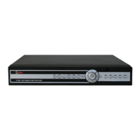
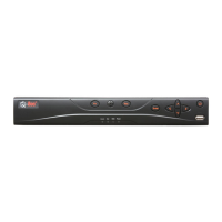
FRONT PANEL
8 Channels QS558
POWER NET HDD
IR
1 2
REAR PANEL
 Loading...