10 11
It is possible to connect more than one displays to the DVR at the same time using the
different video ports, however they will all show the same images and they cannot be
combined. The menu and mouse cursor will appear on every display simultaneously.
INSTALLATION AND
CONNECTION
CHAPTER 2
IMPORTANT! The default resolution of this DVR is 1024 x 768 pixels. Some
monitors smaller than 19” may not display video properly.
Please note that it is important to keep in mind common safety guidelines when installing your
DVR or connecting additional devices – including turning off and unplugging your DVR before
installing internal components.
POWER
The DVR’s power supply plugs into the DC power socket on the back of the DVR. It is
absolutely essential that you only use the power supply that came with the DVR to ensure
proper operation and to avoid damage.
We also recommend that you use an uninterrupted power supply (UPS) so that the system will
continue to operate in the event of a power loss. In addition, you should connect the DVR into
a UL-1449 rated surge protector. It should have a joule rating of at least 400, a response time
of 10 nanoseconds or less and a clamping voltage of no more than 330 volts.
Your DVR will power up as soon as it is plugged in.
When shutting down the DVR, it is essential that you do so by using the Standby feature
within the software or the Standby button on the remote control. Once the display goes
blank, you may either turn off the surge protector or unplug the DVR.
If you wish to restart the DVR from standby mode, then you may do so by pressing and
holding the Standby button on the remote control.
USB PORTS
There are two USB ports on the rear panel of your DVR. Either may be used by the mouse
with the other port being used by a removable or externa USB drive for file backup and
firmware upgrades.
VIDEO DISPLAY
Depending on the model, your DVR can
output video to either a standard VGA
monitor, television or HD display. The monitor
is connected via a VGA monitor cable (not
included) to the VGA port on the rear of the
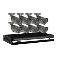
DVR. The television is connected to the BNC
Video Out port on the DVR’s back panel
through the use of the a BNC (Male) to RCA
(Female) adapter cable (Picture 2-1) which
is included with some models. This plugs into
the RCA Video In port on the back of the
television.
Another type of BNC to RCA adapter is
shown in Picture 2-2. This also attaches
to the DVR’s Video Out port but requires a
user-supplied standard RCA cable to connect
from it to the RCA Video In port on the back
of the television.
PICTURE 2-1
PICTURE 2-2
PICTURE 2-3
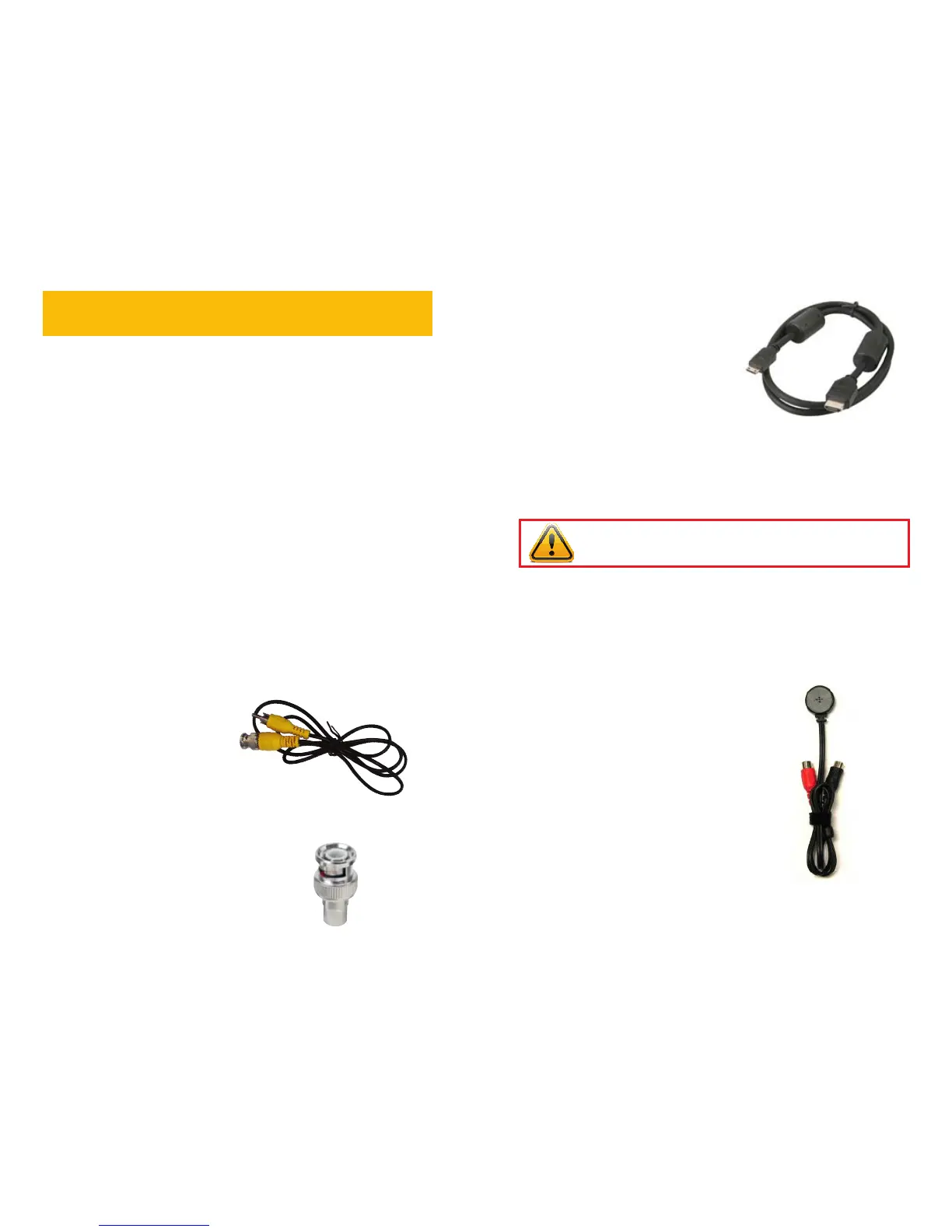
AUDIO
Your system has one or more inputs to allow you to record sound to accompany the video
recording from a camera. This can be accomplished using either an audio-equipped camera
or a microphone co-located with the camera such as Q-See’s QSPMIC (Picture 2-4). The
RCA-style audio plug from the camera must be plugged into the correct port on the back of
the DVR in order for the sound to be recorded to the correct video track.
On DVRs with a single Audio In port, this
audio port will record sound to the first
camera only. Therefore, it is important to
make sure that the camera covering the area
of the microphone is also plugged into the
first Video In port. Systems with two Audio
In ports will record sound to Channels 1 and
2 only. If your DVR features multiple audio
input ports, they are numbered to correspond
with the channel of the same number.
For DVRs featuring an HDMI port on the
back panel, use the included HDMI cable
(Picture 2-3) to connect to an HD monitor or
television.
PICTURE 2-4
 Loading...