TMS STRING PINSPOTTER OWNER’S MANUAL
400-051-010-01 Rev. Date: 7/17 Page 1-7
Major Components and Assemblies
Pinspotter
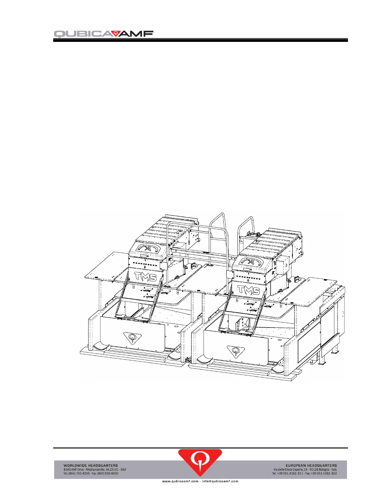
The equipment used to control the setting of the pins is a string pinspotter. The usual
configuration is in pairs and multiples thereof, although single pinspotter configurations
are possible. The pinspotter consists of a number of subassemblies that operate in
coordination with each other to guide the operation of the machine. A large metal box
houses the majority of the moving components. This box rests on a set of two tables
below which are ten pins that are connected to the pinspotter by strings. The machine
and tables are supported by two crossbars that are attached to the kickbacks which also
act to contain and deflect the pins and balls during a game. Directly below the tables is
the area of the lane called the pin deck upon which the pins rest during play. Behind the
pin deck is the pit which is sloped to direct the balls to the exit opening in the kickback
so that the ball can be propelled back to the bowler by the horizontal ball accelerator
located in the space between the pair of pinspotter kickbacks. Behind the pit is a heavy
curtain called a cushion that absorbs the impact of the bowling ball and pins, and at the
front is a shield which raises and lowers during play.
Figure 1, TMS Tenpin Pinspotter Pair
Located just to the right of the left hand pinspotter is the controller also referred to as the
control chassis. This black box contains a computer, liquid crystal display, keypad, and
numerous connectors, switches, breakers, and other electrical components necessary to
control a pair of pinspotters. The controller contains the software used to guide the
 Loading...