TMS STRING PINSPOTTER OWNER’S MANUAL
400-051-010-01 Rev. Date: 7/17 Page 2-13
Procedure 2-3, Pin Brake Adjustment
This feature is used to adjust the clamping force of the brake cams against the strings.
Indications that a brake needs adjustment are: if a pin that should be held up is lowered, a
PIN BRAKE error message on the control chassis display, or a pin that stays up when it
should be lowered. This adjustment needs to be made only if a brake is not functioning
properly and other causes, such as a failed solenoid, bad wire or electrical connection,
encoder wheel holes that have become filled with dust or string debris, broken cam
spring, or damaged or misrouted string have been eliminated as the cause.
1. If it is not already ON, turn on power to the pinspotter. Apply LOTO before opening
covers with supplied tool (key).
Warning: High voltage is present in the pin detector circuit board assembly.
2. From the chassis, select the Brake Adjust function using either the pin detector
circuit board pushbuttons (preferred) or the control chassis keypad.
The drawbar will drive to the rear of the machine and then drive forward. The pin
brakes momentarily energize as the drawbar continues to the front of the machine.
3. Remove AC power and apply LOTO constraints. Unlock and open the front and top
covers to access the pin brake assemblies that are underneath the pin detector.
The pin brake assemblies at the ends of the pin brake array (located under the pin
detector circuit board assembly) are easily accessible. If you need to adjust a pin
brake that is located below the pin detector circuit board assembly, perform step 5;
otherwise, skip to step 6.
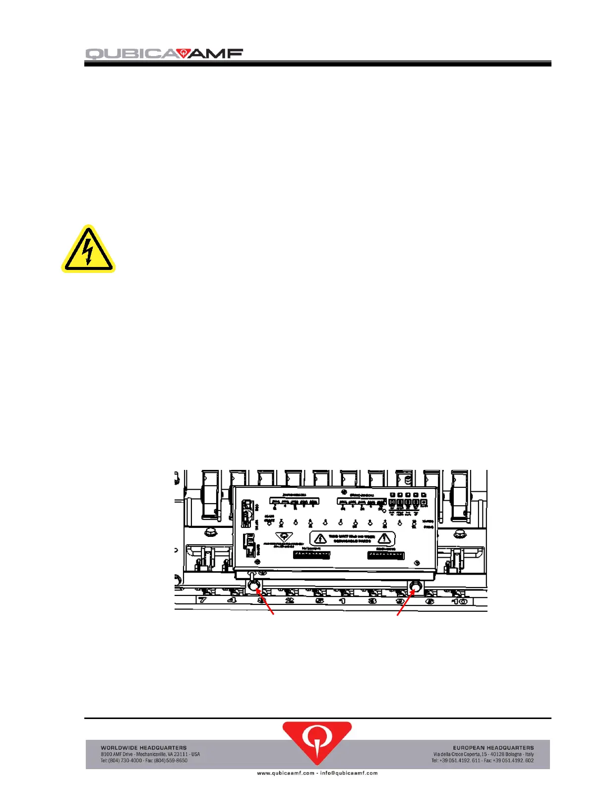
4. Remove the two screws that secure the pin detector circuit board assembly mounting
brackets to the machine (see Figure 2-3) and move the assembly out of the way.
Figure 2-3, Pin Detector Circuit Board Assembly
 Loading...