TMS STRING PINSPOTTER OWNER’S MANUAL
400-051-010-01 Rev. Date: 7/17 Page 2-14
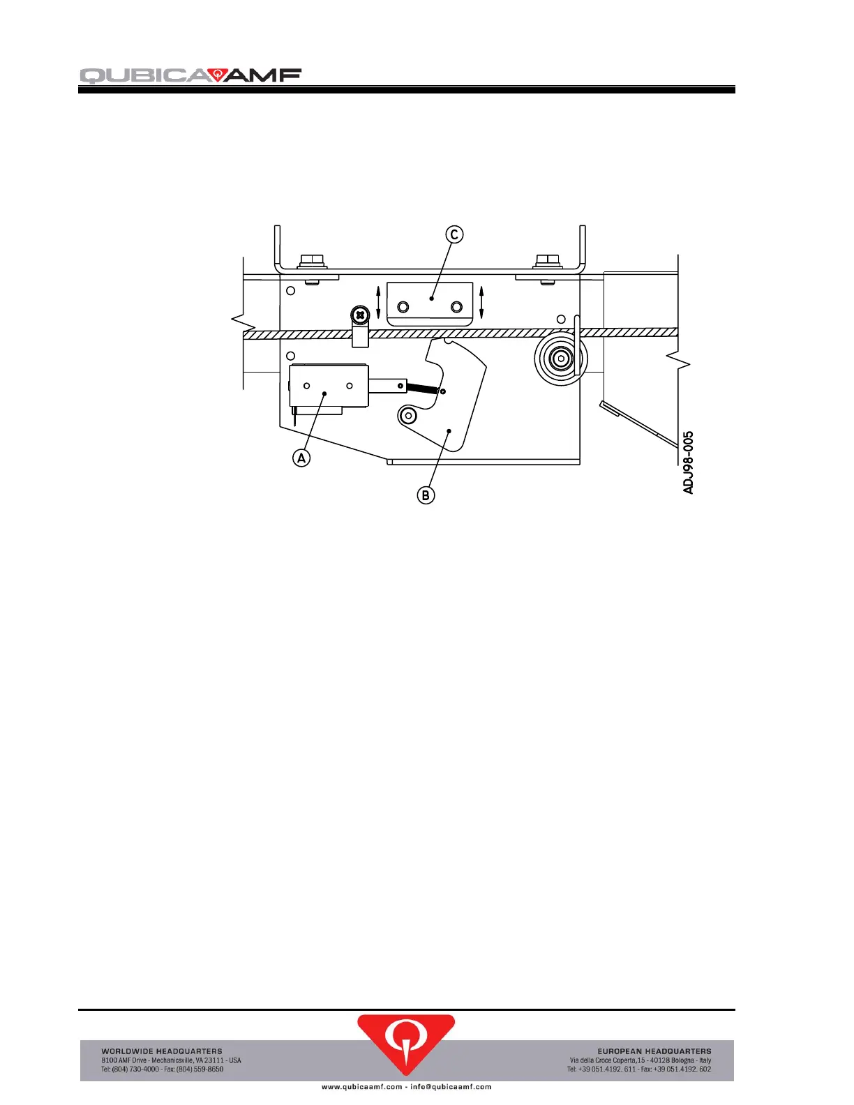
5. Adjust the clamping pressure by loosening the two screws that secure the brake angle
plate to the assembly and moving the plate up to decrease or down to increase the
clamping pressure (see Figure 2-4). Try to maintain the original angle of the plate
and only move it a small amount. Tighten the screws.
A – Solenoid
B – Brake Cam
C – Brake Angle Plate
Figure 2-4, Pin Brake Assembly
6. Reinstall the pin detector circuit board assembly. Close and secure the top cover.
7. Remove LOTO and energize the machine.
8. Test the adjustment by pressing the Brake Adjustment pushbutton on the pin
detector circuit board. Repeat the adjustment as necessary. Apply LOTO before the
top or front cover is opened.
9. Close covers and remove LOTO.
10. When the adjustment has been completed, press the EXIT pushbutton on the control
chassis keypad to exit the Mechanics Mode and to lock the keypad.
 Loading...