Issue 1.5 Q-Drive Installation Manual
Copyright © 1996 Quin Systems Ltd. Page 19
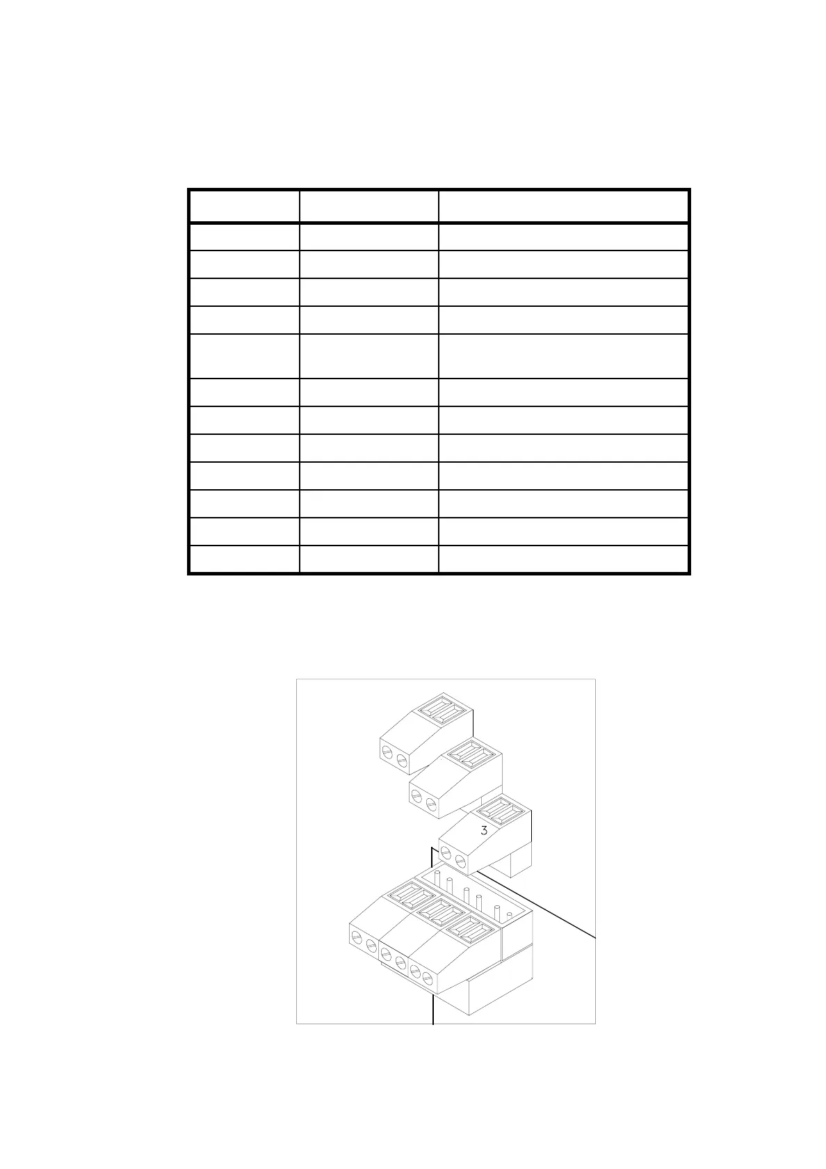
4.2.5 P10, P11 & P12
These connectors are used for interfacing all other low voltage signals to the drive and
are detailed below in Table 8: Figure 6. shows the pin 1 & 2 socket of connector P10,
P11 & P12 already inserted into their respective mating half, whilst the pin 3 & 4
connectors are shown waiting to be inserted.
Figure 6. P10, P11, P12: discrete signals
Pin Number. Signal Name. Function.
P10.1. Earth. Command shield connection.
P10.2. Gnd. Drive internal Ground (not isolated).
P10.3. S+. Command signal +ve.
P10.4. S-. Command signal -ve.
P11.1. EXTILIM. External current limit,+10V
corresponds to max peak current.
P11.2. +12V Bat. External 12V battery +ve.
P11.3. RDY2. Volt free drive ready relay contact.
P11.4. RDY1. Volt free drive ready relay contact.
P12.1. -12V Bat. External 12V battery -ve.
P12.2. BGnd. External 12V battery Gnd.
P12.3. 024V. 0V for ENABLE signal.
P12.4. ENABLE. Drive enable signal from controller.
Table 8: P10, P11, P12 Connections
P
1
2
2
1
1
2
0
1
P
1
3
4
P
3
4
1
0
4
1
1
P
2