Issue 1.5 Q-Drive Installation Manual
Copyright © 1996 Quin Systems Ltd. Page 15
4.2 Low Voltage Connections
Details of the low voltage connections which include the Encoder, Resolver, RS422/
RS232 and discrete signals, are described in the following sections.
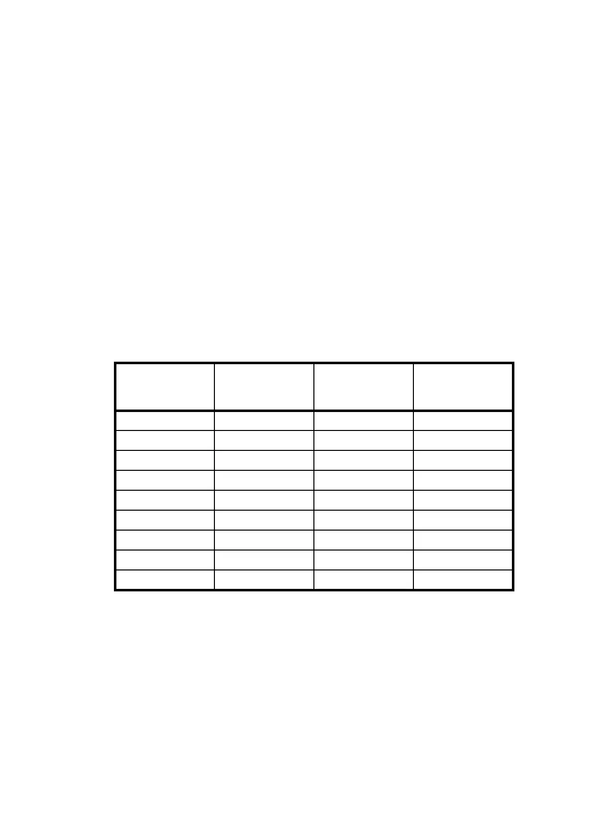
4.2.1 P2 Upper: Resolver
The resolver interface uses the upper half of connector P2 and is wired as shown in
Table 4: and Figure 4. . The external screen should be connected at both ends; motor
and amplifier. The overall screen must be connected at the amplifier end, pin 1 should
be used, and it should also be connected to the motor earth terminal at the motor end of
the cable. It is recommended that the three internal screens should be connected only at
the servo-amplifier end of the cable. They should be connected to pin 8 along with the
Ref. 2 connection. Pins 2 and 3 of the connector are used for the motor thermal overload
which can be either normally open or normally closed, or (if a thermal sensor is used)
have the following characteristics:
Contacts Open: >10kΩ
Contact closed <1kΩ
P2 Pin Number Function
Suggested Wire
Colour
SEM Motor
Resolver
connector
1ScreenBraid J
2 Thermal Trip 1 White T
3 Thermal Trip 2 Brown S
4 Sin 2 Pink E
5Sin 1GreyC
6 Cos 2 Yellow P
7Cos 1GreenD
8Ref. 2Blue B
9Ref. 1Red A
Table 4: P2 Upper, Resolver Input Connections