Issue 1.5 Q-Drive Installation Manual
Copyright © 1996 Quin Systems Ltd. Page 9
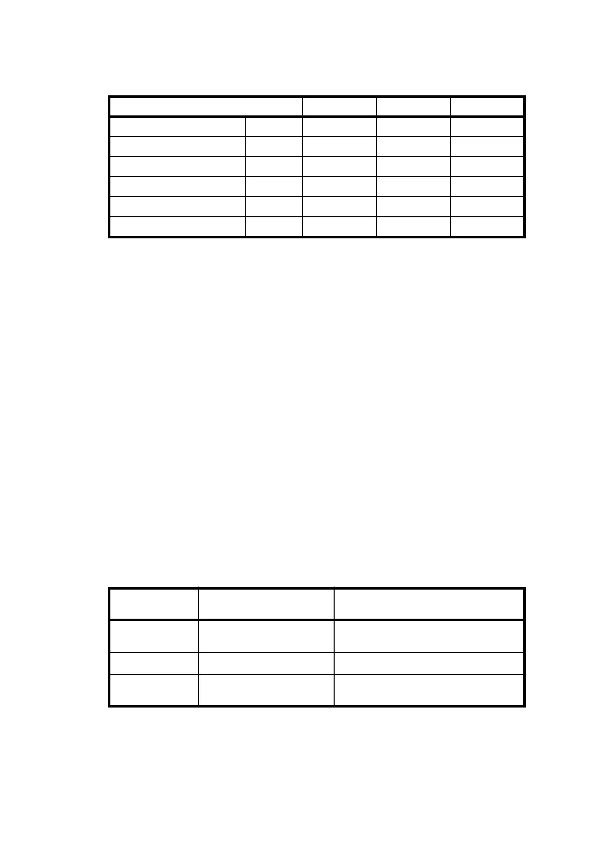
3.4.2 Drive Performance Specification
Note:
I
rms
= I
peak
/ 1.41
P =1.73 x I
rms
x V
rms
or P= 3 x I
rms phase
x V
rms phase
- in star V
rms phase
= 210V / 1.73
I
rms phase
= I
rms
- in delta V
rms phase
= 210V
I
rms phase
= I
rms
/ 1.73
Example: Type PQD506 I
rms max
= 11.8 A
rms rated
= 5.9 A
P
max
= 1.73 x 11.8 x 210 = 4.3 kW
P
rated
= 1.73 x 5.9 x 210 = 2.1 kW
3.4.3 Analogue readings on the motherboard
The Q-Drive motherboard contains several measurement points which permit an
analogue reading of the three signals shown in Table 2-
The location of the measurement points is shown in Figure 24. on page 61
Servo-amplifier type
:
PQD506 PQD510 PQD518
Rated rms current Amps 5,9 10,0 18,7
Rated peak current Amps 8,3 14,2 26,4
Max. rms current Amps 11,8 20,1 37,3
Max. peak current
Amps 16,7 28,4 52,8
Rated power (kW) 2,1 3,6 6,8
Max. power (kW) 4,3 7,3 13,6
Table 1: Drive Data
Measurement
point
Description Scaling
Current Instantaneous Current 10V corresponds to the max. current of
the unit
Command Internal command voltage V
command
= V
ext. cmd
Speed Motor speed +/- 10V corresponds to the max. speed
of 6000 rpm
Table 2: Test Points