Q-Drive Installation Manual Issue 1.5
Page 16 Copyright © 1996 Quin Systems Ltd.
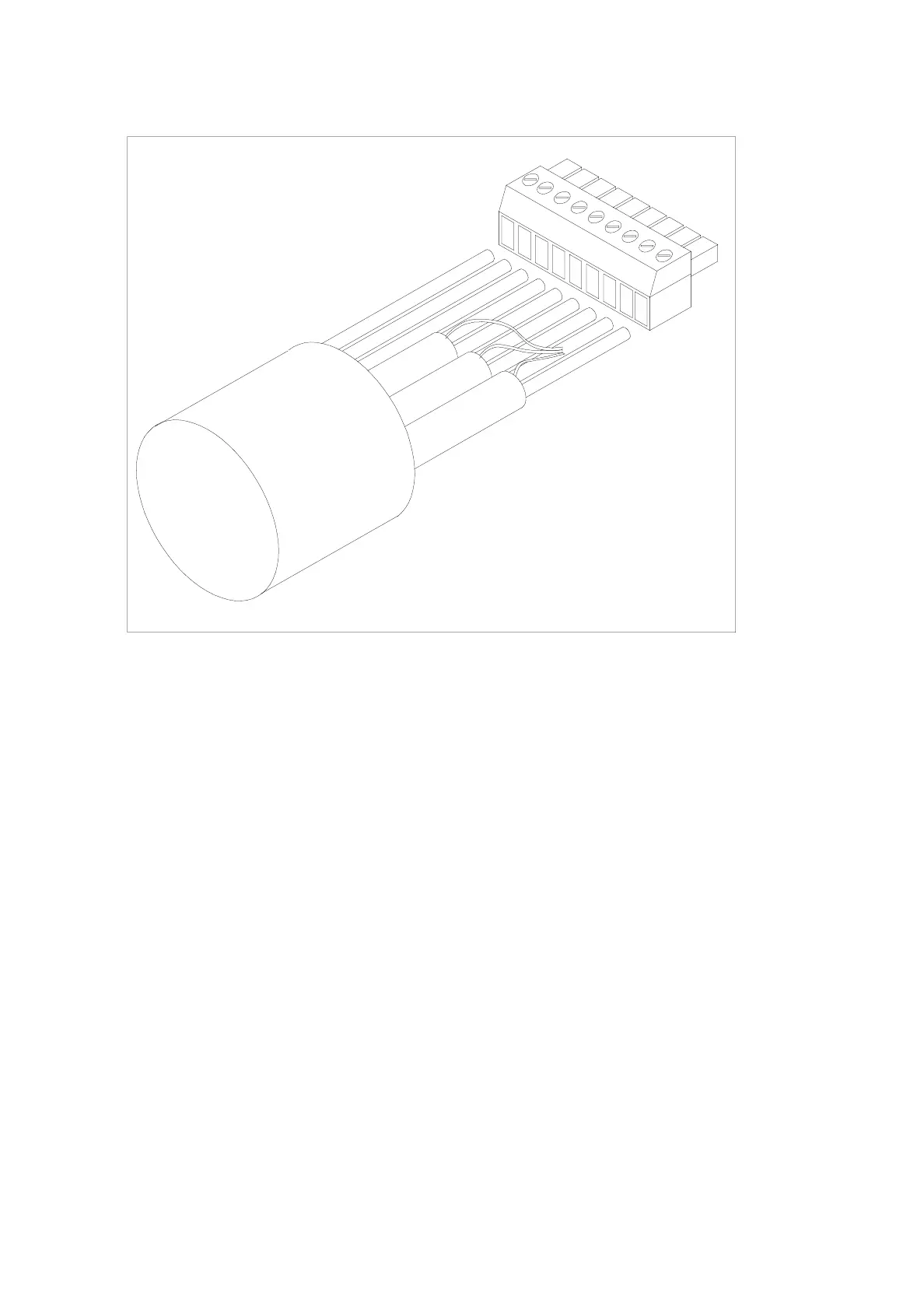
Figure 4. P2 Upper: resolver connector
4.2.2 P2 Lower: Encoder
The Encoder output uses the lower half of connector P2 and is wired as shown in Table
5: and Figure 5. . The Q-Drive servo amplifier simulates an incremental encoder using
the positional information obtained from the resolver. The encoder resolution can be as
high as 1024 pulses per revolution (PPR) when the drive speed is limited to 3500 RPM.
If the drive is required to move the motor at higher speeds then the encoder resolution
drops to a maximum of 512 PPR. If the drive is set to 1024 PPR and 6000 RPM then an
incorrect encoder pulse train will be produced.
The cables used for the encoder signals should be high quality screened cables, using
individually screened twisted pairs, with an overall cable screen as well. The cable
screen should be connected directly to the main earth point, not via the control system
0V supply.
It is recommended that the maximum cable length for the encoder output should not
exceed 25m, which should not be a problem as the Q-drive and control system can
usually be mounted within the same cabinet. If the machine installation requires a cable
longer than 25m, then it may be necessary to install an additional line driver unit to
boost the encoder signals.
Screen
Heidenhain cable
type 200 775 02
7
6
5
Yellow
Grey
White
Brown
Pink
Green
Blue
Red
3
2
1
4
8
9