Issue 1.5 Q-Drive Installation Manual
Copyright © 1996 Quin Systems Ltd. Page 23
5. Electrical Installation
5.1 General
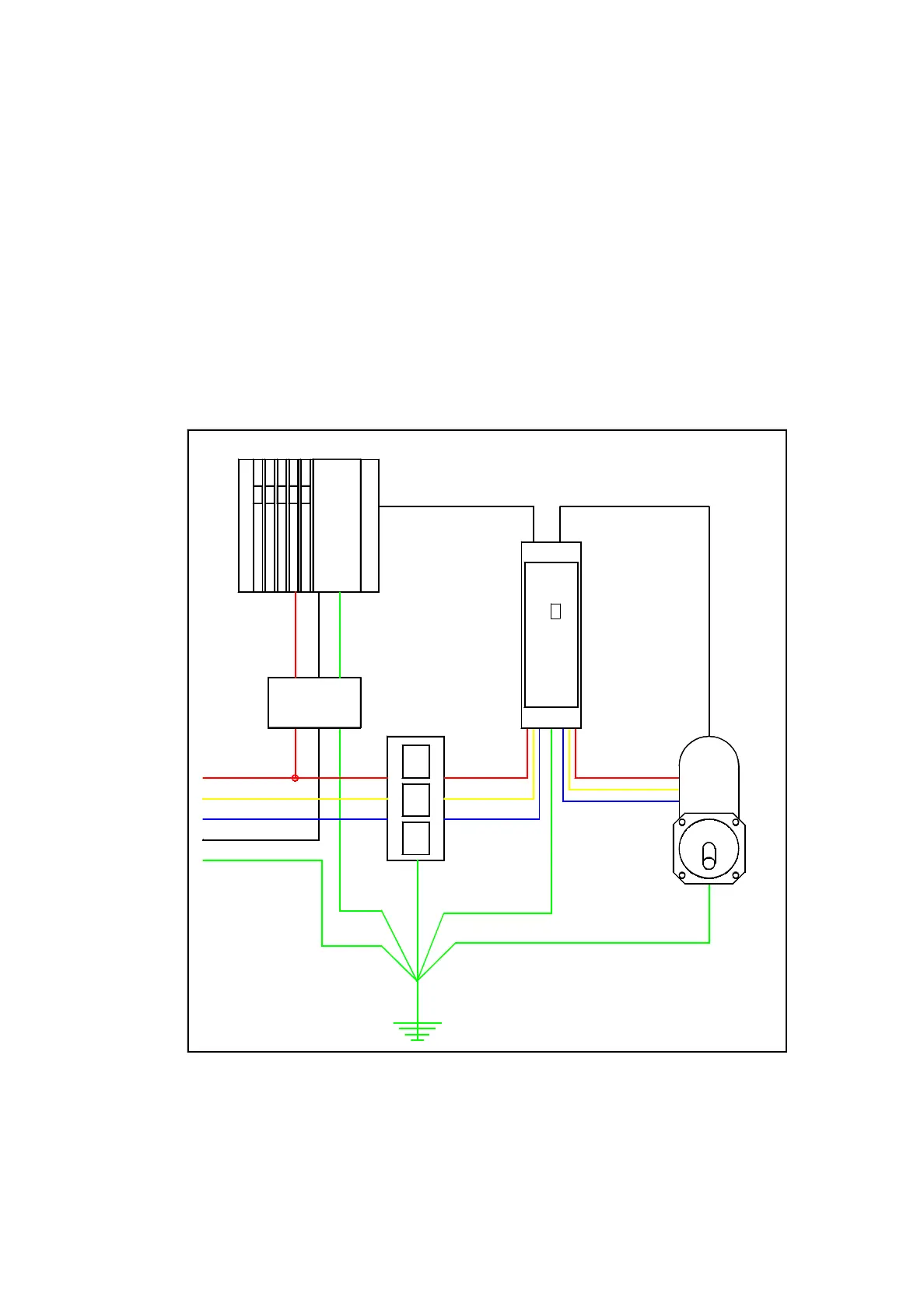
This section gives some guidelines for the electrical installation of the drive amplifier
system. The diagram below shows a typical installation, and is used to highlight
specific areas described in the following sections. Note that this is only a very
simplified sketch, not a full installation wiring diagram. Details such as isolators,
contactors and other switching arrangements are not shown but in most cases will be
used. Please refer to the motor and control manufacturer’s instructions for further
details on electrical installation
Figure 9. General installation arrangement
Q-Drive
Resolver cable
Neutral
Earth
ø3
ø1
ø2
3 ø
Isolating
Transformer
Encoder cable
1 ø
Isolating
Transformer
Control System
8
8 8
QUIN
8
8
8
Motor