Cardiac Stress Treadmills Service Manual Theory of Operation 2-1
2
Theory of Operation
Overview
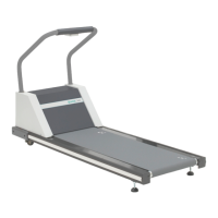
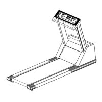
The treadmill consists of two subassemblies: the headframe and the deck
and roller assembly. The stress monitor, which is attached by cable to the
treadmill, functions as the user interface.
The user enters all treadmill commands through the stress monitor system
with the information appearing on the monitor’s display. The stress
system processes the information and sends commands to the headframe
assembly.
Headframe Assembly
The headframe assembly receives speed and grade commands from the
stress monitor. The assembly includes the drive and grade systems and the
electronics that drive these systems. A three-phase AC motor drives the
walking belt. A DC motor moves the front of the treadmill up or down to
simulate hills. The drive motor supplies torque and speed to the drive
pulley through a drive belt.
Deck and Roller Assembly
The deck and roller assembly is attached to the headframe and supports
the rear of the treadmill. It provides the platform for the walking belt. The
drive belt supplies torque to the walking belt through the drive roller
pulley.
Stress Monitor to Treadmill Interface
The TM treadmill communicates with the stress monitor through a
standard RS232 interface. The ST treadmill communicates with the stress
monitor through an RS422 interface.