4-4 Repair/Replacement and Calibration Cardiac Stress Treadmills Service Manual
♦ Recommended: vacuum the internal components before replacing the
hood or applying power. Use caution near the AC Drive Module. Do not
vacuum the drive board on the AC Drive Module.
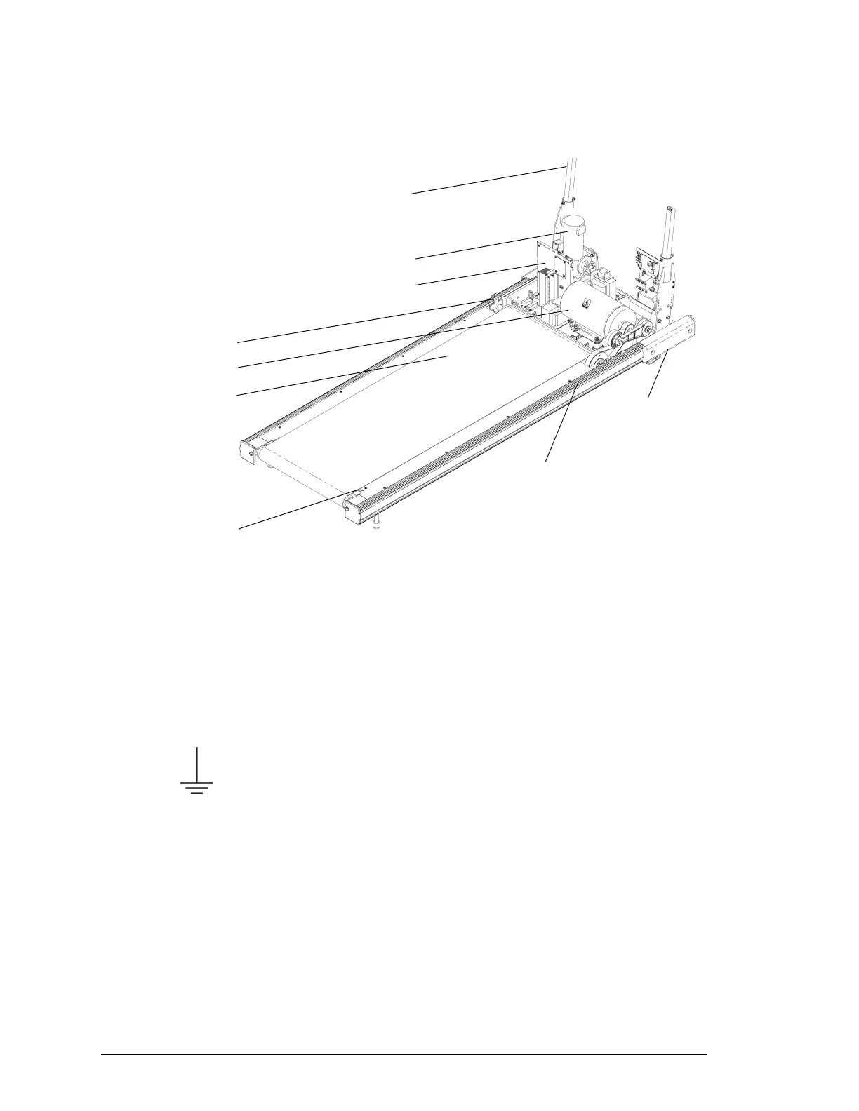
Treadmill with Hood Removed
Replacing the Configuration Plate
On low voltage units, the configuration plate module includes the power
cord, which is attached to the plate. On high voltage units, the power cord
is removable and is not part of the configuration plate module.
1. Remove the power cords and treadmill hood as described in
“Removing the Treadmill Hood” on page 4-3.
2. Remove the two ¼-20 screws that attach the power cord ground wires
to the headframe. The screws are located in the center of the
headframe—protective ground is represented by the ground symbol
shown to the left. Be sure to rewire correctly.
3. Cut the plastic ties and remove the configuration plate connections.
Remove the communication cable. Note the wire colors and
connection points
4. Remove the two ¼-20 screws that hold the configuration plate to the
headframe.
Caution! Hold the plate so that it doesn’t fall.
5. Replace the configuration plate module following steps 2 through 4 in
reverse order.
6. If no other service is required, replace the treadmill hood as described
in step 9 on page 4-3.
Siderail
Walking Belt
Front Roller
Bumper
Grade Motor
Drive Motor
AC Drive Module
Roller Guard Screws
Rack Gear