4-6 Repair/Replacement and Calibration Cardiac Stress Treadmills Service Manual
5. Unplug the isolation transformer wires.
6. Unplug the non-isolation transformer wires.
7. Unplug the grade potentiometer wires. Clip the plastic ties around the
cage only, not around the headframe.
8. Unplug the limit switch wires.
9. Unplug the power resistor wires.
10. Unplug the drive motor wires.
11. Unplug the configuration plate wires.
12. Remove the four Phillips screws securing the AC Drive Module.
13. Remove the AC Drive Module and return it to with an authorized
return number to authorized technical support.
14. Reassemble using steps 2 through 13 in reverse order.
15. If no other service is required, replace the treadmill hood as described
in step 9 on page 4-3.
Bus Recovery System (BRS)
The Bus Recovery System (BRS) uses a bleeder resistor to protect the
treadmill from high voltage damage when the treadmill is used at high
grade.
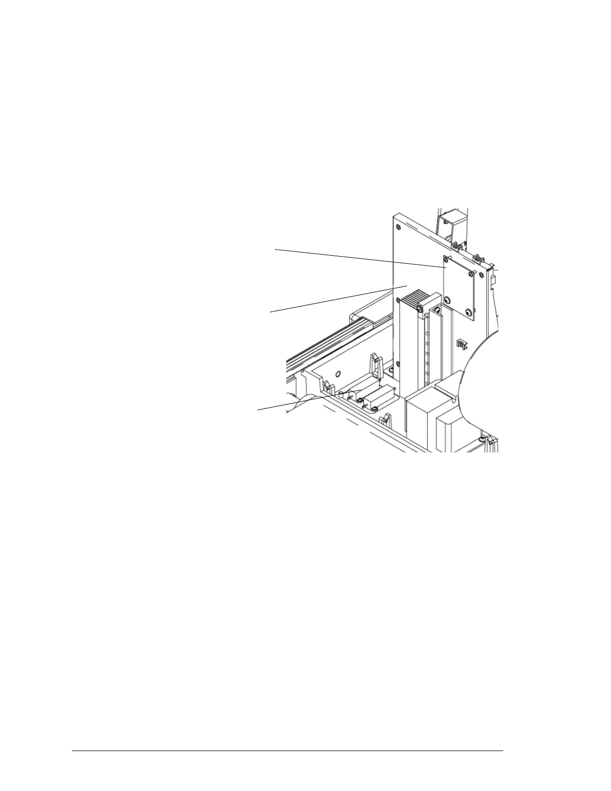
Two gold BRS resistors are wired together, then wired to a connector that
plugs into the AC Drive Module. The resistors are located on the right
side of the head frame near the drive roller (see previous figure).
To replace the BRS resistors:
BRS Resistors
AC Drive Module
Digital Interface Board
(TM Model Only)