Page 125 of 254
7.2 Connection diagram
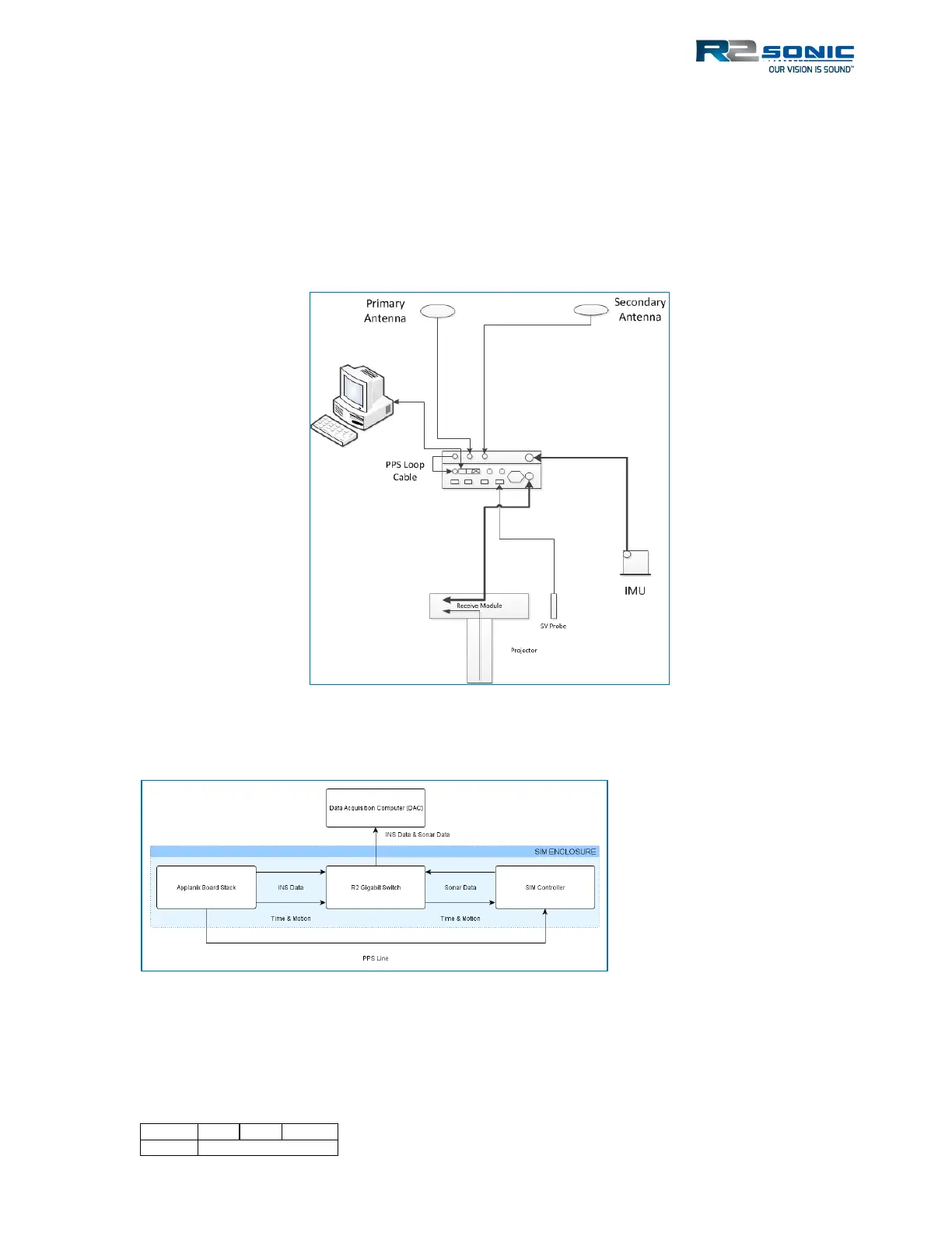
When using the INS, there is no need to provide inputs for the motion or the time stamp, as those
are provided internally through the SIM’s Gigabit switch. The only serial connection is the sound
velocity probe that is on the sonar head. A PPS loop cable is required to go from the PPS out to the
PPS in.
Figure 146: INS connections
Figure 147: INS SIM block diagram
 Loading...