Page 194 of 254
Part No. 96000001
13.6 SIM Installation – AUV
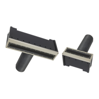
The circuit boards, inside the SIM, can be supplied separately as a SIM Stack (see below images). The
three boards use a PC/104 size format, but do not use the PC/104 bus. The three boards are the I/O
board where the customer connects time, motion and sound velocity sensors; SIM Controller board;
and a gigabit Ethernet switch.
It’s best that the SIM Controller board supply power to the sonar head as the controller board has a
common mode choke for the 48 VDC power to the sonar head, and the SIM Controller board can
control power to sonar head. If the customer uses their own custom data acquisition software, a list
of commands for the sonar head and SIM are in Appendix VIII. The uplink data format is provided in
Appendix IX.
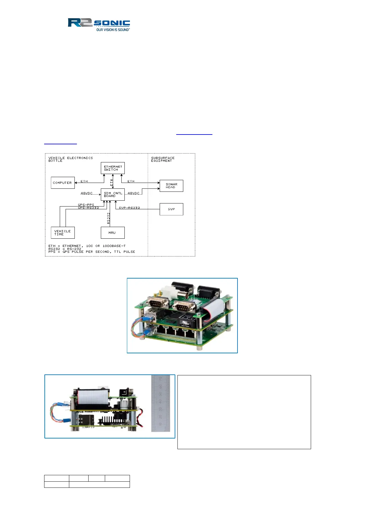
Figure 202: GPS (ZDA or UTC formats) and PPS signals supplied by the vehicle time system
Figure 203: SIM Board Stack
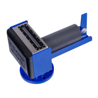
Figure 204: SIM Stack height
Top board: I/O
Middle board: SIM controller
Bottom board: Gigabit, 5-Port, Ethernet
switch
BNC connector: GPS PPS input
SMB connectors: sync in and out