Do you have a question about the R2Sonic 2026 and is the answer not in the manual?
Overview of R2Sonic MBES modules, GUI, SIM, and sonar head functionality and connections.
Guidance on using the manual and standard measurement units utilized throughout the document.
Technical specifications for the Sonic 2026 multibeam echosounder system.
Technical specifications for the Sonic 2024 multibeam echosounder system.
Technical specifications for the Sonic 2022 multibeam echosounder system.
Physical dimensions and dry/wet weights for Sonic 2026 components.
Physical dimensions and weights for Sonic 2024 components.
Physical dimensions and weights for Sonic 2022 components.
Details electrical interface specifications including power, consumption, and data interfaces.
Table showing ping rates for various ranges based on sound velocity.
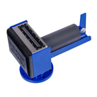
Instructions for mounting the sonar head's receive module on a standard R2Sonic mounting frame.
Detailed steps for mounting the receive module, showing topside and face views.
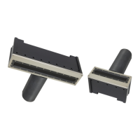
Describes receive module connectors and cable connections, emphasizing proper seating.
Explains the change to a locking ring design for the deck lead connector, commencing August 2016.
Details new cable clamping arrangements introduced in 2017 for increased robustness.
Explains receiver cable clamp configuration and screw types for securing the cable.
Describes the projector cable clamp, its parts, and updated housing requirement.
Instructions for securing the projector to the frame with standoffs and connecting cables.
Details mounting the 2026 projector using isolation collars, washers, and nuts.
Guidelines for orienting the sonar head (forward or aft) and selecting orientation in software.
Recommendations for pre-deployment testing, including communication and receiver/transmitter tests.
Importance of proper sonar head installation for data quality and stability.
Importance of proper sonar head installation for data quality and stability.
Typical employment of over-the-side mounts for shallow water or temporary survey needs.
Describes moon pool mounting as a stable arrangement for sonar head deployment.
Hull mount as the sturdiest mounting option, physically attached to the vessel's hull.
Ideal for ROV operations due to size and low power, requires Ethernet communication.
Overview of the SIM as the communication center for Sonic MBES, detailing its role.
Details the SIM's physical installation requirements, connection, and securing methods.
Explains SIM connections: DB-9, BNC, Ethernet, and mains power.
Details serial communication using standard RS-232 protocol with pin assignments.
Explains the need for GPS PPS and NMEA ZDA for accurate time stamping.
Connects GPS PPS and time messages to the SIM for synchronization.
Details supported formats (TSS1, iXSea, MiniPOS3) for motion data input.
Explains the use of SVP input for sound velocity probes.
Describes connecting SVP probes via serial or Ethernet.
Details the miniSVS probe connection and baud rate settings.
Lists supported sound velocity formats for SIM input.
Steps for installing Sonic Control GUI on a Windows-based computer.
Lists useful keyboard shortcuts for navigating Sonic Control features.
Accesses sonar setup and configuration options for communications and parameters.
Guides on setting up Ethernet parameters (IP, Subnet Mask, UDP) for system communication.
Configures computer network settings (IP, Subnet Mask) for initial communication.
Utilizes the Discover function to identify and configure attached R2Sonic equipment.
Lists default IP and BasePort configurations for Head, SIM, GUI, and sensors.
Explains INS IP address configuration and timing for setting it.
Describes sending data via broadcast to multiple computers using IP and Subnet Mask.
Details network settings for Subnet Mask and GUI IP for proper configuration.
Configures communication parameters for sensors via serial or Ethernet.
Sets up GPS, Motion, and SVP interfacing over Ethernet, agreeing with sonar configuration.
Input for ZDA or Trimble UTC messages, PPS pulse for synchronization and timing.
Data for roll stabilization, supporting TSS1, iXSea, and MiniPOS3 formats.
Notes that Heading input is not currently enabled.
Configuration for sound velocity probe communication.
Configuration for receiving or sending synchronization TTL pulses for ping timing.
Accesses sonar operational settings for system tailoring via menu or mouse.
Selects operating frequency in 10 kHz steps, changeable on the fly.
Enables 700 kHz for Ultra High Resolution, requires Type 1006 projector.
Suggestions for operating at 700 kHz, increasing power and absorption.
Enables 90-100 kHz operation for deeper surveys for Sonic 2026.
Sets a limit on the ping rate to reduce file size or for other reasons.
Selects swath sector from 10° to 160°, affecting sounding density.
Controls sector coverage symmetrically about nadir using the mouse cursor.
Allows asymmetric sector adjustment using the Shift key and mouse.
Directs the sector to port or starboard to map vertical features or areas of interest.
Blocks noise or interference close to the sonar head by setting a minimum range.
Offers Equiangular or Equidistant modes, further enhanced by Dual/Quad mode.
Spatially distributes acrosstrack bottom sampling for ROV/AUV operations.
Shows current Bottom Sampling Mode (BSM) and indicator for mode changes.
Provides highest sounding density per ping, up to 1024 soundings.
Adapts system to survey tasks: normal, vertical feature, or FLS mode.
Displays acoustic intensity in the wedge for setting operating parameters.
Configures Forward Looking Sonar in Wide or Narrow modes.
Adjusts FLS image 'gain' and selects color palette in Display options.
Operates FLS in stealth mode, transmitting only when user manually triggers via Ping button.
Utilizes steerable projectors for pitch stabilization and FLS mode beamwidth control.
Stabilizes data for vessel roll motion and counteracts vessel pitching.
Configures system for dual head operation: simultaneous or alternating pings.
Loads specific settings files for dual head configuration.
Turns on/off TruePix, Snippets, Water Column, and Intensity features.
Optimizes NIC settings for water column data flow and buffer size.
Enables pinging at different frequencies with each ping for advanced backscatter analysis.
Enables pinging at different frequencies with each ping for advanced backscatter analysis.
Designed for UHR systems to switch between UHR and standard modes for linear features.
Configures ocean characteristics like Absorption and Spreading Loss for beam steering.
Sets absorption based on frequency and water chemistry, using a calculator.
Sets spreading loss, generally unaffected by frequency, for deeper water surveys.
Explains TVG computation using absorption, range, spreading loss, and gain.
Defines TVG curve shape by Absorption and amplitude by Spreading Loss.
Importance of accurate sound velocity for beam steering and error correction.
Configures projector orientation, Z offset, and head tilt for optimal installation.
Sets projector orientation (forward or aft) for accurate data orientation.
Sets the vertical offset of the projector relative to the receive array.
Enters tilt angle if sonar head is physically tilted to port or starboard.
Displays current system parameters, firmware versions, and serial input messages.
Provides detailed system status for sonar head and SIM, including serial data.
Monitors sonar receiver signal level and sets parameters for meaningful backscatter.
Visualizes real-time imagery using TruePix monitor, requires Sonic Control to be open.
Accesses engineering commands, firmware updates, and snapshot features.
Area for engineering commands for troubleshooting or system analysis.
Procedure to update SIM and sonar head firmware, disabling firewalls and virus checkers.
Addresses potential issues with firewalls and virus checkers during firmware upgrades.
Details the special update process for transmitter firmware.
Captures GUI images using hotkeys and resets sector rotation.
Accesses help topics, options, and remote assistance features.
Opens an electronic copy of the Operation Manual for assistance.
Displays installed system upgrades and their enabled status.
Allows R2Sonic support to remotely assist with setup or troubleshooting via internet.
Shows the version of Sonic Control to ensure compatibility with sonar firmware.
Customizes measurement units and color schemes in the Sonic Control window.
Changes display units to US Survey Feet for axes, sound velocity, and depth.
Selects imagery data formats (TruePix, Water Column) and applies bathy gate settings.
Details TruePix and Water Column format sizes and data rates.
Captures GUI images into video files using the Record button.
Automatically adjusts Power, Pulse Width, and Gain based on Range and saturation.
Configures Robo feature for auto gain adjustment based on range and saturation.
Controls main operating parameters like Range, Power, Pulse Width, and Gain.
Sets the maximum slant range and determines the ping rate and listening time.
Automatically sets correct range and optimizes ping rate based on water depth.
Sets source level of transmit pulse for good acoustic returns.
Determines transmit pulse duration time, affecting resolution and power.
Adjusts the receive gain of the sonar head receivers in 2 dB steps.
Allows elimination of noise by setting limits in Minimum and Maximum Depth.
Manually adjusts depth gates using the mouse in the wedge display.
Automatically adjusts gates based on water depth and selected tolerance.
Automatically adjusts gates for depth and bottom slope, disabling manual controls.
Explains data loss if gates eliminate valid data and data collection software handling.
Records the entire GUI in x.264 format (*.mkv) using ffmpeg.exe.
Tool to obtain range and bearing information within the GUI using the mouse cursor.
Loads default configuration files to save local changes or reset GUI to factory defaults.
Guides on running Sonic Control on a different computer for data collection.
Detailed steps for setting up Sonic Control on two computers for operation.
Procedure to revert Sonic Control operation back to a single computer setup.
Block diagram illustrating the main components of the sonar head.
Explains the projector's operation and transmit patterns at different frequencies.
Describes how the receive module converts acoustic energy and forms beams.
Block diagram of the SIM, showing its main components and interfaces.
Block diagram of the SIM, showing its main components and interfaces.
Lists the physical components of the R2Sonic I2NS, including SIM, antennas, and IMU.
Describes the Type 82 IMU, its housing, and updated vertical offset.
Illustrates connection diagrams for INS components and the SIM block diagram.
Details installation procedures for IMU, GPS antennas, and INS connections.
Details mounting requirements for IMU and GPS antennas for clear sky view.
Explains BNC and TNC connections for PPS and primary antenna.
Describes DB9 connections for serial communication and GNSS board access.
Guides on setting up Sonic Control for Applanix IP address and network configuration.
Resets Applanix IP address via R2Sonic GUI if connection is lost.
Details specific Applanix Group 119 data fields for R2Sonic SIMINS.
Configures interface type and Ethernet for receiving internal sensor data.
Monitors INS data values and accuracy limits.
Explains measuring offsets from vessel's COG to INS components.
Describes IMU types 42 and 82, their differences, and vertical reference.
Lists dimensions and mass for I2NS components and electrical specifications.
Provides drawings for I2NS Type 42 IMU.
Presents dimensional drawings for the I2NS Type 42 IMU.
Shows dimensional drawings and offsets for the I2NS Type 82 IMU.
Provides a drawing of the I2NS Sonar Interface Module (SIM).
Measuring offsets for each sensor relative to its reference point.
Defining the central reference point (CRP) and measuring physical offsets to sensors.
Vital step for accurate survey data; measuring offsets using tape and plumb-bob.
Refers to appendix for measurements relative to system offsets on mounting frame.
Describes measuring offsets using metal tape, with multiple people.
Details measuring Z offset and draft using plumb bob and tape measure.
Critical alignment of sonar head to motion sensor/gyro for depth accuracy.
Importance of sonar head orientation for slant range to depth conversion and position accuracy.
Collecting data over different seafloor topographies for latency, pitch, and yaw tests.
Testing latency using survey lines up a steep slope at different speeds.
Collecting data over a flat seafloor twice in reciprocal directions for roll offset.
Collecting pitch data over steep slopes, requiring precise path alignment.
Difficult test using parallel lines on either side of a feature or slope for yaw offset.
Order of solving tests (latency, pitch, roll, yaw) and handling large errors.
Evolution of multibeam calibration and development of the Patch Test.
Order of computing patch test values and general criteria.
Common errors in patch test data collection, focusing on positioning.
Accuracy of positioning systems (DGPS, RTK) and errors related to water depth.
Preference for well-defined features over slopes for pitch and yaw calibration.
Deeper water provides better results for DGPS accuracy and feature definition.
Importance of steering reference for sonar head to ensure exact location matching.
Speed considerations during latency tests to avoid squat or settlement errors.
Allowing time for motion sensor to settle and helmsman to find heading for accuracy.
Checking for repeatable position of deployable hydrophone poles.
Methods to improve patch test results through data collection and computation.
Importance of collecting ample data for reliable statistical results and identifying out-of-trend values.
Computing each patch test value independently based on previous test results.
Verifying patch test results by finding a singular object and processing data.
Main concern in multibeam is sound in water, influenced by velocity and coherence.
Major influence on acoustic energy propagation, requiring sound velocity casts for accuracy.
General salinity ranges and impact of salinity changes on sound velocity.
Temperature's major influence on sound velocity and influencing factors.
Errors caused by wrong velocity profiles, affecting swath shape and depth accuracy.
Factors affecting acoustic energy in water, including transmission losses.
Energy spread over larger area, reducing density, not frequency-dependent.
Acoustic energy spreading evenly in all directions from the source.
Acoustic energy trapped within boundaries, radiating horizontally.
Frequency-dependent conversion of acoustic energy to heat in water column.
Graphs showing sound absorption at various frequencies and temperatures.
Discusses sea surface, bottom, and volume reverberation effects on acoustic energy.
Ethernet link preferences, data rates, and filtering for ROV/AUV installations.
Rules for twisted pairs in Gigabit and 100BASE-T Ethernet connections.
Typical Ethernet data rates for Bathymetry, TruePix, Snippets, and Water Column.
Illustrates single and dual head ROV installation schemes A and B.
Specifies power requirements for Sonic MBES systems with SIM and head components.
Minimizing common mode noise on 48VDC power line using common mode chokes.
Details SIM controller board power connections and connector mating.
Discusses SIM installation options in ROV top-side or vehicle, with block diagrams.
Describes SIM installation in AUV as a SIM Stack, including component boards.
Guidelines for physical installation of SIM boards, static sensitivity, and options.
Explains LED status indicators on I/O, SIM Controller, and Gigabit switch boards.
Provides dimensional information for SIM Controller board installation.
Shows images of assembled SIM boards and SIM stack height.
Instructions for dual sonar head installation and operation.
Covers dual head configuration options: simultaneous or alternating pings.
Loading factory default settings for dual head configuration.
Describes commands sent from the user interface to the sonar head and SIM.
Notes on command formats, byte order, data types, and recommended sending rates.
Lists Ethernet port numbers for Head, SIM, and GUI commands.
Defines data types like u8, u16, u32, s8, s16, s32, and f32.
Pseudo C format for commands, including packet name and value.
Table of head commands, their formats, units, values, and descriptions.
Table of SIM commands, their formats, units, values, and descriptions.
Commands to control GUI functions remotely, sent to GUI Baseport + 7.
Command line switches for defining video recording and multiple GUI instances.
Examples of commands sent to sonar head and SIM with hex, integer, and float representations.
Describes data formats sent from the sonar head and SIM in pseudo C.
Notes on data section headers, byte order, data types, and packet types.
Lists port numbers for various data types related to GUI Baseport.
Defines data types like u8, u16, u32, s8, s16, s32, and f32.
Lists maximum Ethernet data rates for Bathymetry, TruePix, Water Column, and Snippets.
Detailed format of Bathymetry Data packets, including header and data sections.
Detailed format of Snippet Data packets, including header and snippet data.
Format for Water Column data, including magnitude and optional phase data.
Format for Acoustic Image data, including header and magnitude sections.
Format for TruePix data, providing magnitudes and direction angles.
Reports status of the sonar head, useful for troubleshooting.
Reports miscellaneous information from the SIM box for troubleshooting.
Device status packet contains ConfigID for IP configuration, ignored for data collection.
Guides on testing data collection systems using captured data and Bit-Twist.
Requires knowledge of Ethernet communication for data playback.
Capturing sonar data using Wireshark with specific capture options.
Editing MAC and IP addresses in packets using bittwiste.exe.
Playing back data using bittwist.exe or recommended Wireplay.exe.
List of figures with their corresponding page numbers for easy reference.
Dimensional drawing of the Sonic 2024/2022 projector.
Dimensional drawing of the Sonic 2026 projector.
Dimensional drawing of the Sonic 2024/2026 receive module.
Drawing showing receiver outline with penetrator details.
Dimensional drawing of the Sonic 2022 receive module.
Drawing showing horizontal offset for Sonic 2022 receiver/projector.
Dimensional drawing of the Sonic 2024 mounting bracket.
Dimensional drawing of the Sonic 2022 mounting bracket.
Dimensional drawing of the Sonic 2026 mounting bracket.
Drawing of the Sonic 2024/2022 mounting bracket flange.
Dimensional drawing of the SIM box enclosure.
Outline drawing of the SIM stack.
Drawing showing minimum passage dimensions for R2Sonic deck lead connector.
Drawing of the locking ring type deck lead.
Dimensional drawings for I2NS Type 42 IMU.
Shows offsets for the I2NS Type 82 IMU.
Drawing illustrating the I2NS IMU cable pinout.
Dimensional drawing of the I2NS SIM.
Diagram showing theoretical offsets for dual head mounts.
| Brand | R2Sonic |
|---|---|
| Model | 2026 |
| Category | Marine Equipment |
| Language | English |