Page 185 of 254
Appendix VII ROV and AUV Installation
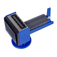
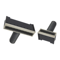
13 APPENDIX VII: Sonic MBES Mounting: Sub-Surface (ROV/AUV)
13.1 Installation Considerations
• A 1000BASE-T link (best time sync accuracy) is preferred; however, with bathymetry only
information, 100BASE-T will work. 10BASE-T will also work but is not recommended. Bathy
data requires 2 Mb/s data rate at a maximum ping rate of 60 pings/sec. For future
compatibility, please use 100BASE-T at a minimum, Snippets will not work with 10BASE-T;
however, Snippets will work over a 100BASE-T link.
• Average power, for a Sonic 2024 is 50W (1A), peak is 100W (2A); for a Sonic 2022 it is 35W
(0.73A), peak is 75W (1.5A). The peak power of 100W (75W) occurs just after transmit and
typically lasts for a few msecs (depends on transmitter power setting). If you use a separate
power supply for the sonar, we recommend using a 120 to 150W power source to supply the
head, but less if installing a Sonic 2022.
• The sonar up/downlink is all done through the Ethernet channel. Thus, no other hardware is
required except for the Ethernet media converters (copper to fibre, fibre to copper). As a
precaution, placing additional filtering on the output of the 48V supply to the sonar head is a
good idea to prevent vehicle electronic noise from getting into the sonar head. A common
mode choke, on the 48V line, is recommended. The Bourns (JW Miller) PM3700-50-RC
common mode choke works well (surface mount part). A Bourns 8102-RC choke, which is
easier to install (non-surface mount), can also be used.
• R2 Sonic supplies two types of deck cables. Only the Ø14mm deck cable (Part # 16000002) is
rated to 3000 meters water depth. Do not substitute this cable, as the Ethernet data pairs
need to meet certain important specifications. When terminating the Ethernet connections
to your connector, the Ethernet twisted pairs need to terminate right at the connector
pins, maintaining the twist on the wires as close to the connector pins as possible. On the
bulkhead connector, use CAT5, or better Ethernet cable, from the connector to the Ethernet
media converter. Use adjacent pins for each wire pair. If 100BASE (or 10BASE) Ethernet is
used, only the green and orange pairs are required. All four pairs, including blue and brown,
are only required when using Gigabit Ethernet.
• Using a connector with a pigtail spliced on to the deck leads’ Ethernet pairs has a low
probability of working. If the deck lead must be terminated to a pigtail, the pigtail length
must be as short as possible, probably no more than 7-8cm. There are no special
considerations for the power conductors other than the connector being able to handle
48VDC and 2 amperes. The drain (shield) wire does not need to be terminated.