Page 66 of 254
Part No. 96000001
5.5 Sensor Setup (Serial and Ethernet Interfacing)
The Sonar system receives various data on the SIM serial ports or via the Ethernet. Select Settings |
Sensor setting to setup the communications parameters.
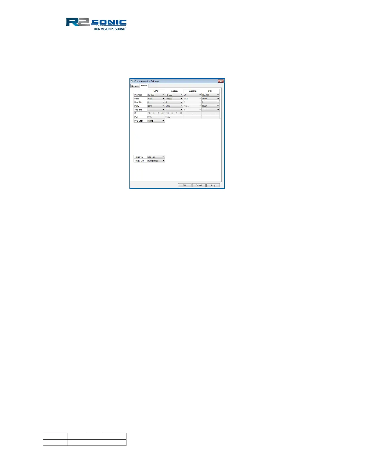
Figure 53: Sensor serial communication settings
5.5.1 Ethernet Interfacing
The system will accept the GPS time message, Motion, and SVP over Ethernet as well as the normal
serial connection. When setting up the Ethernet interfacing, the IP and Subnet Mask settings, for
the auxiliary sensor, must agree with the sonar’s Ethernet configuration. The data must also utilise
UDP. The same UDP port can be used for all inputs, but separate UDP ports are suggested. Enter the
sending sensor’s IP.
In the dropdown for Interface, select Ethernet. When selected, the IP and Port fields will become
active. Set an IP that agrees with the rules of the subnet mask (default subnet is 255.0.0.0) and the
UDP port. The LED’s, on the SIM, will turn green when data is received the same as with serial data.
Using the default sonar Ethernet configuration, with a Subnet mask of 255.0.0.0 and the sonar’s IP
set to 10.xxx.xxx.xxx, the auxiliary sensor’s network configuration has to be set up with the same
Subnet mask (255.0.0.0) and use similar IP addressing (10.xxx.xxx.xxx). The illustration below shows
the IP address based on the default sonar network configuration.