Page 57 of 254
4.1.3 Serial Communication
All serial interfacing is standard RS-232 protocol.
Table 12: DB-9M RS-232 Standard Protocol
Table 13: SIM DB-9M Serial pin assignment
4.1.4 Time and PPS input
4.1.4.1 Connecting PPS and Time to the SIM
To provide the most accurate multibeam data possible, the Sonic MBES requires the GPS Pulse Per
Second (PPS) and NMEA ZDA time message or an ASCII UTC message, which is associated with the
pulse, to accurately time stamp the Sonic MBES data. The data collection software may take in the
same PPS and time message to synchronise the computer clock and the auxiliary sensor data.
The PPS is a TTL (transistor-transistor logic) pulse. The SIM box PPS input threshold is ≈ +1.35V with
about 0.14V of hysteresis. The PPS input rejects pulses narrower than about a microsecond to reject
high-frequency cable reflections and ringing, but not all types of noise. The input pulse timing needs
to be stable, within about 100ppm, or the SIM box will reject the pulses, and the LED will flash red
instead of green. The pulse is transmitted to the SIM, and the data collection computer via a coaxial
cable (such as RG-58); the cable is terminated with BNC connectors so that it is easy to use a ‘T’
adaptor to parallel the PPS to different locations. Connect one end of the coaxial cable to the GPS
receiver’s PPS output (via a ‘T’ adaptor, if required) and the other end to the SIM BNC labelled PPS.
When a pulse is received, the LED next to the BNC connector will flash green at 1 Hz.
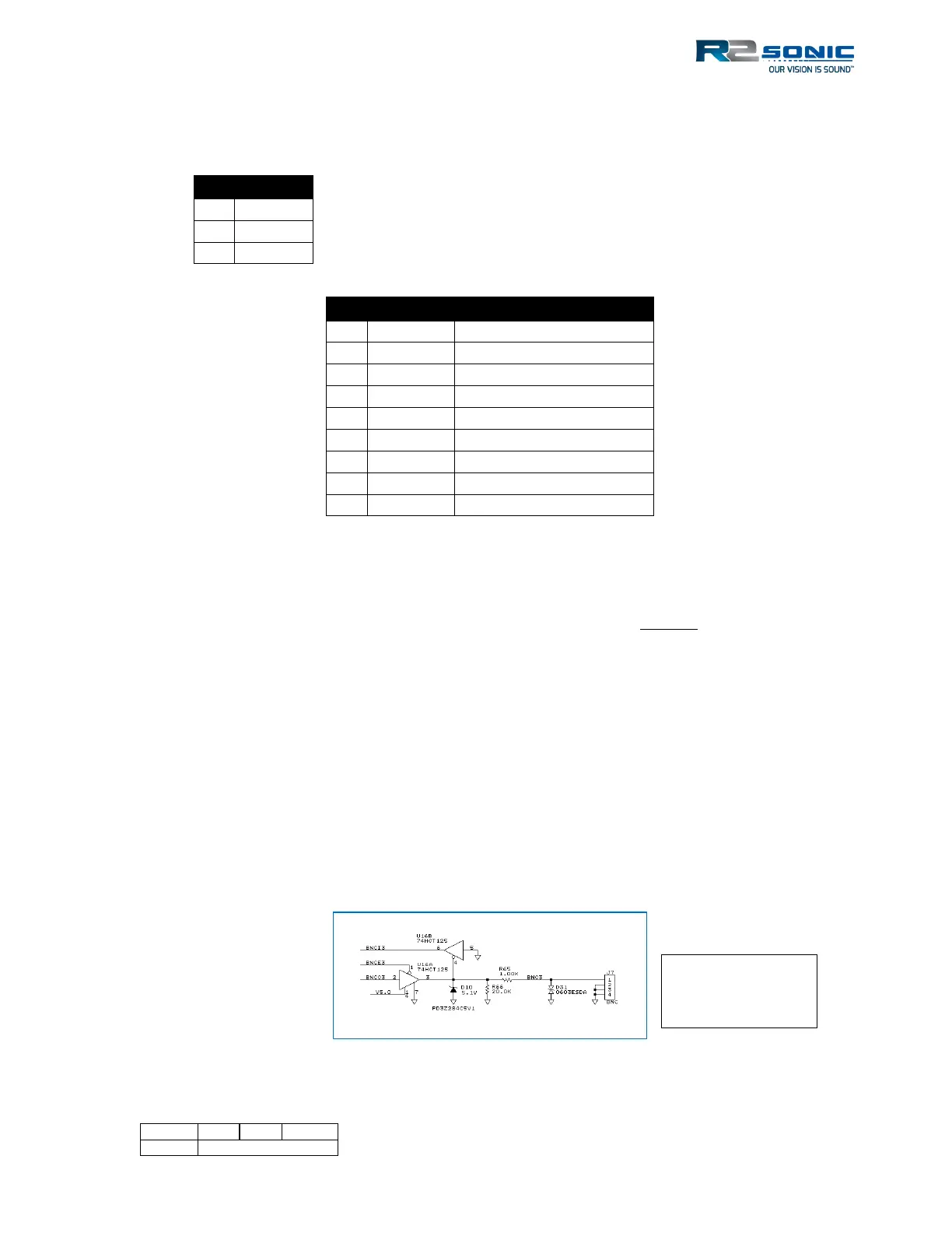
Figure 43: TTL input/output (PPS and Sync In/Out) schematic
(electrostatic discharge)
protection; it trips at