Page 159 of 254
APPENDIX IV: Offset Measurements
10 APPENDIX IV: Offset Measurements
10.1 Lever Arm Measurement – Offsets
Each component or sensor that produces information, unique to its position, will have a point that is
considered the reference point of that sensor. The Sonic MBES, the motion sensor, and the GPS
antenna will have a documented point from which to measure. The gyrocompass’ data is not
dependent on its position on the vessel so, therefore, does not require an offset measurement.
10.2 Vessel Reference System
When all equipment (Sonic MBES sonar head, motion sensor, gyrocompass and GPS) have been
permanently mounted, the physical offsets to a central reference point (CRP) must be measured.
The central reference point (CRP) or vessel reference point (VRP) is that point that the surveyor
chooses to be the origin for the X and Y grid that will define the horizontal relationship between all
of the sensors. The vertical or Z reference can be the water line or another logical vertical reference.
Generally, the CRP corresponds to the centre of gravity or rotation of the vessel. All of the sensors
must have their physical relationship to each other measured and entered into the data collection
software or the processing software.
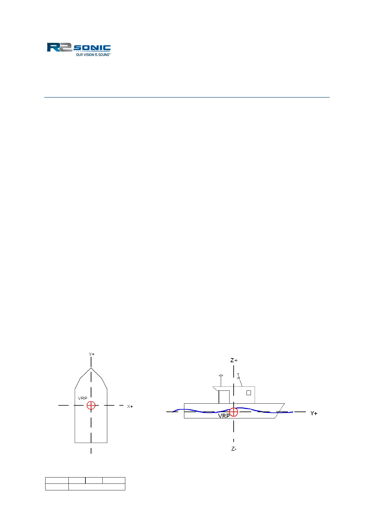
All offsets, between sensors, are defined by an X, Y and Z offset from a reference (CRP or VRP) point.
In most survey software, the X-axis runs athwartship, i.e. from the port side to the starboard side;
the Y-axis runs alongship from the bow to the stern. The Z-axis runs perpendicular through the
reference. The origin is usually located at the vessel’s centre of gravity or centre of rotation. The
sign convention is standard for a Cartesian plane, translated to a vessel: starboard of the reference
point is positive, forward of the reference point is positive. The sign for Z may differ, depending on
the data collection or processing software.
Figure 175: Vessel Horizontal and Vertical reference system