Page 68 of 254
Part No. 96000001
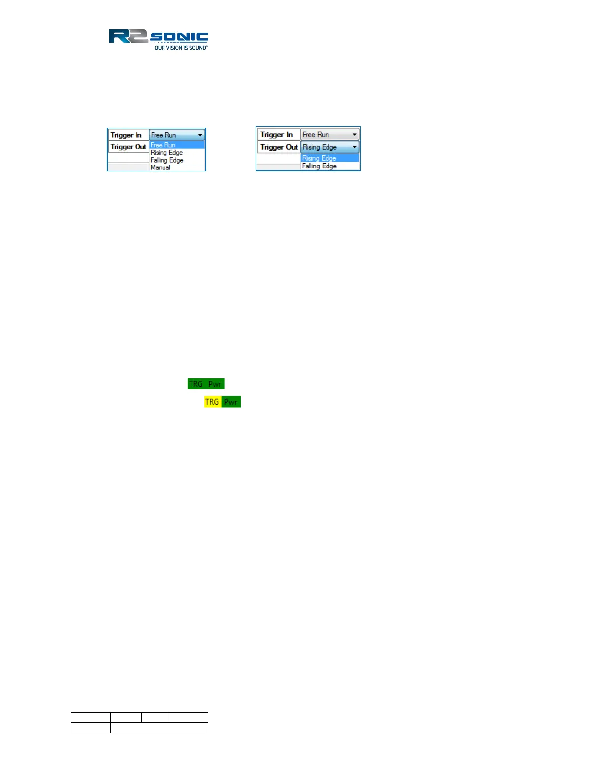
5.5.6 Trigger in / Trigger out
Used to receive or send synchronisation TTL pulses. Output goes high when transmitter pings, goes
low after the receiver has collected data.
Figure 55: Trigger In/Out Options
5.5.6.1 Trigger In
• The SIM Synch In input requires a TTL signal (0 to +5V)
• The minimum high-level trigger point is +2.4V
• The trigger pulse width must be longer than 1µsec
• The sonar will ping 10.025msecs (±10µsecs) after receiving the trigger
5.5.6.2 Trigger Out
• Output is 0 to +5V
• If Trigger Out is set to Rising Edge, the output pulse is high during the receive period. If the
Trigger Out is set to Falling Edge, the output pulse is low during the receive period.
In the lower portion of the GUI, the colour indicator will indicate when the Trigger In is active by
turning from grey to green . When the Trigger In mode is set to Manual, the colour
indicator will change to yellow . Manual mode allows the sonar to ping every time an
external Ethernet command (PNGØ, 1) is sent to the sonar head or the GUI or if in FLS mode, the
Ping button is used.