© 2020 Radiodetection Ltd 19
4.18 Measure mode
The transmitter has the capability of providing
impedance measurements by determining the resultant
impedance across the crocodile clips of the Direct
Connection lead while connected to the utility. These
measurements can be useful when assessing sheath
fault severity. It is also possible to measure potential
voltage that may be present on utilities to warn of
potentially dangerous or harmful voltages present.
In measure mode the measurement is derived from an
AC signal applied to the utility from the transmitter
Impedance & voltage measurements
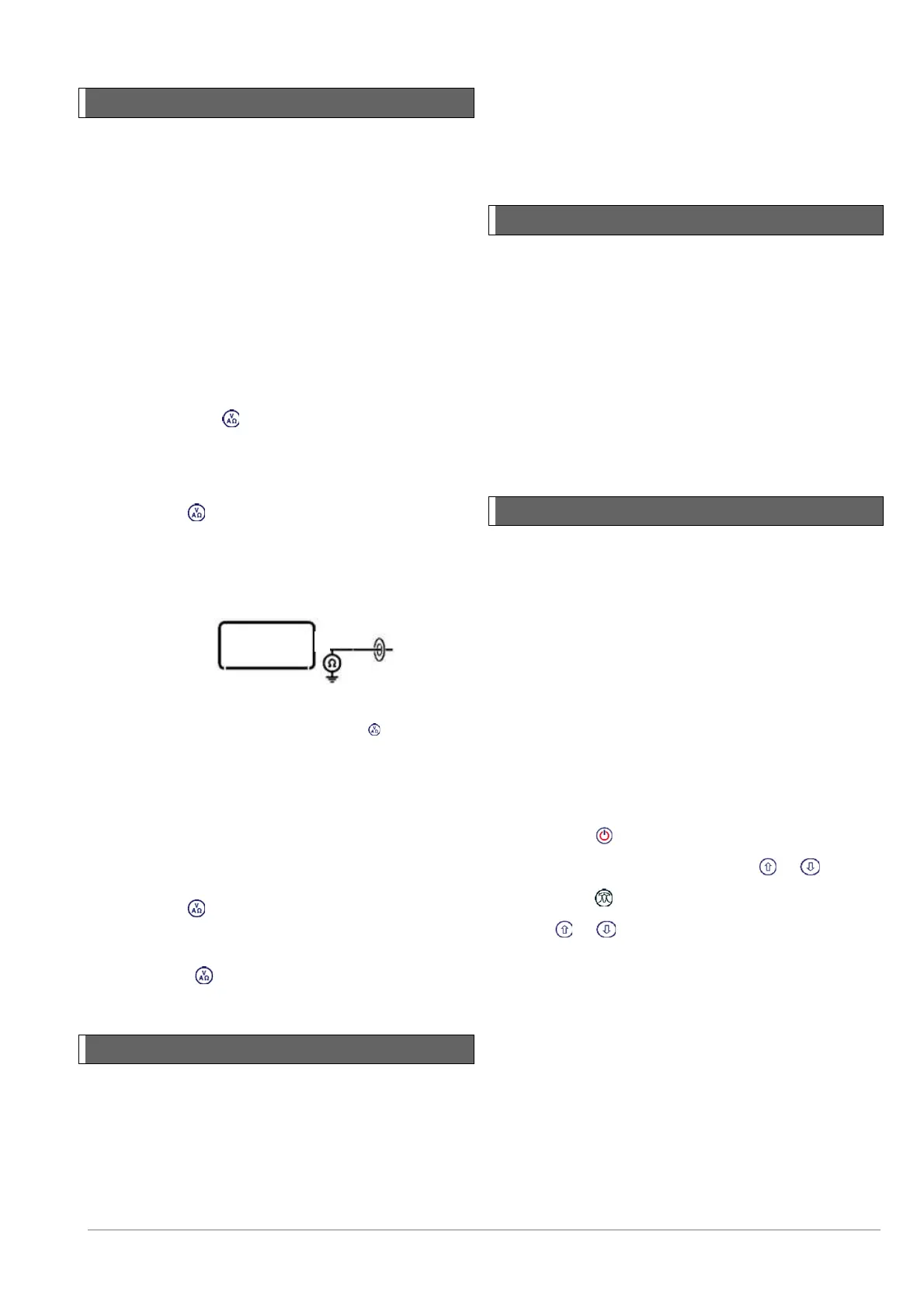
1. Connect the Direct Connection leads to the utility
and switch on the transmitter.
2. Hold down the key until MEAS is displayed and
the measuring icon is activated.
The transmitter display will now indicate the voltage
level measured across the connection leads.
3. Press the key once and the display will indicate
the impedance measured across the connection
leads.
The measurement icon will display the following
symbols:
Figure 4.13 Impedance and voltage measurements
4. To exit MEAS mode hold down the key until the
display reverts back to the normal operating screen.
Impedance measurements using
active frequency
1. Connect the Direct Connection lead to the utility and
switch on the transmitter.
2. Select the preferred frequency and output the signal.
3. Press the key once and the display will indicate
the impedance measured across the connection
leads and also the output power of the transmitter.
4. Press the key once to return to the normal
operating screen.
4.19 CALSafe™
Usage logging equipped RD8100 locators can be set to
disable them once they are beyond the expected service
/ calibration date.
When the unit is within 30 days of the service due date
the unit will display at startup the number of days left.
The locator will stop functioning on the service due date.
CALSafe™ is disabled by default. You can edit the
CALSafe service due date, and enable or disable the
function using the RD Manager PC software package.
Refer to the RD Manager operation manual for further
information.
4.20 Usage-Logging
RD8100 logging and GPS locator models feature a
powerful data logging system which records all the
instrument’s critical parameters (including GPS position,
if available) and warnings in its internal memory each
second.
The automatic logging system is always active and
cannot be disabled. Its memory is capable of storing at
least 500 days of normal usage data – based on 8 hours
operation per day. Logs can be retrieved using the RD
Manager PC application for usage analysis and survey
validation. Refer to the RD Manager operation manual
for further information.
4.21 GPS (GNSS)
The RD8100 locator can be paired to an external GPS
device or use its internal GPS module when fitted to
detect and store its latitude, longitude and accurate UTC
time alongside its locating data using SurveyCERT™+
or the automatic logging system (GPS and Usage-
Logging equipped models only).
The presence of GNSS data allows for the data to be
mapped easily and to export and save the information
directly into GIS systems.
For more details on connecting to and sharing data with
an external device, refer to Section 12.
GPS menu
To enter the GPS menu:
1 Press the key to enter the menu
2 Scroll to the GPS menu using the or keys
3 Press the key to enter the GPS menu
Use the or keys to scroll through the 5 options:
RESET: Select YES to reset the internal GPS
(GPS equipped models only)
INT: Select this to use the internal GPS if
present
EXT: Select this to use the GPS from a
compatible paired device
OFF: Select this to switch off the internal GPS
module and save battery
SBAS: Select this to switch ON or OFF SBAS
(Satellite-Based Augmentation System).
SBAS can improve GPS accuracy, particularly
in N.America