© 2020 Radiodetection Ltd 46
6 Plug the clamp into the transmitter output socket.
7 Put the clamp around the pipe or cable and ensure
that the jaws are closed. Switch the transmitter on.
The display will show the Clamp connected icon
Figure 13.7 Clamp connected icon
The line should be grounded (earthed) on each side of
the clamp for the signal to transfer to the line. Ground
the line if necessary. An insulated cable may be traced
even if it has no actual ground connection, providing a
reasonable length is buried either side of the clamp to
provide capacitive coupling to ground (earth).
NOTE: It is not necessary to make a ground connection
from the transmitter when using the clamp.
Transmitter clamp range
Although transmitter and locator clamps look the same,
they have different internal windings. To prevent the
wrong clamp being connected, transmitters and locator
clamps have plugs of a different orientation.
Standard signal clamps
The standard clamps apply the transmitter signal very
selectively and effectively to a target cable up to 130mm
(5¼”) in diameter using frequencies from 8kHz to
200kHz
The standard and small clamps have a double spring
action for positive toroidal contact.
Small signal clamp
The small signal clamp is useful for applying signals from
8kHz to 200kHz to a target cable in a pedestal or other
place with limited space. The clamp is suitable for cables
up to 50mm diameter.
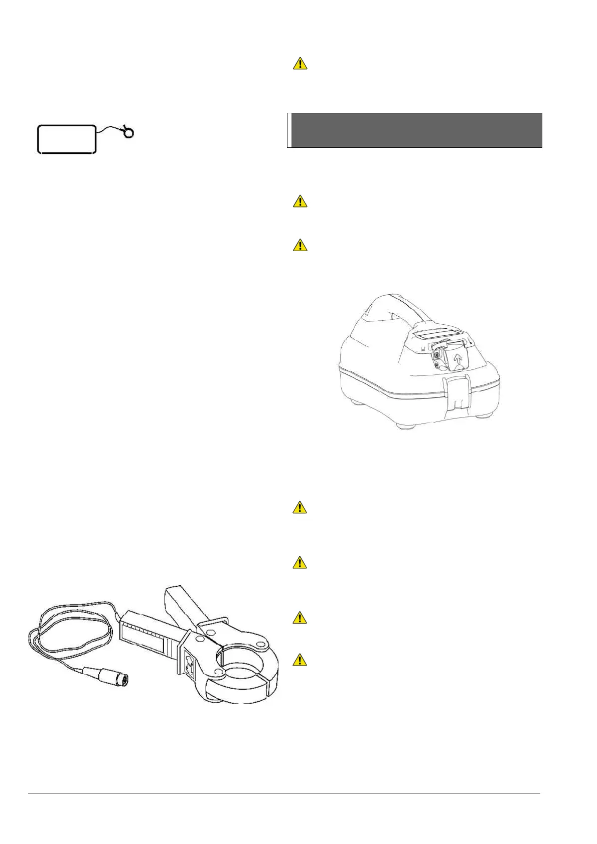
Current Direction (CD) clamp
The CD clamp plugged into the accessory socket of the
transmitter enables CD signals to be applied to individual
cables.
WARNING!. The transmitter must only be connected to
live services using the appropriate accessory such as a plug
connector or live cable connector.
13.5 Transmitter external power
supply
The external Mains or vehicle power supplies provides
an alternative and convenient method of powering the
transmitter.
WARNING!. The mains power supply rating are: 100-
240VAC, 1.3A. Always use an adequately rated detachable
mains lead.
WARNING!. The mains power supply is not IP rated
and should not be used in wet locations
Figure 13.9: Transmitter DC Input
To use the mains or vehicle power supply units connect
them to the DC input socket in the transmitter before
connecting them to the mains or vehicle supply socket.
WARNING! The mains PSU supply cable is the
disconnecting method for isolating the unit from the main
supply.
WARNING! The battery compartment lid is the
disconnecting method for isolating the unit from the battery
supply.
WARNING! Do not position the equipment so it is
difficult to disconnect the unit from each supply.
WARNING! Protection will be impaired if used in a
manner not specified.
Figure 13.8: CD clamp