EasyManua.ls Logo

Rae RAEGuard 2 PID - Wiring Procedure

Rae RAEGuard 2 PID
88 pages
Print Icon
To Next Page IconTo Next Page
To Previous Page IconTo Previous Page
Loading...
RAEGuard 2 PID User’s Guide
12
6.4 Wiring Procedure
1. Inside the housing bottom, unplug the two green terminal block
plugs from the terminal block on the PC boards.
Note: The terminal block plugs accept 12 AWG to 24 AWG wire.
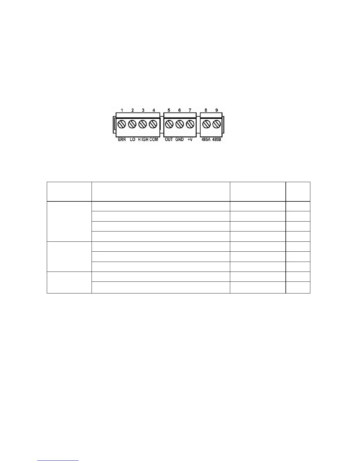
2. Lace the wires through the RAEGuard 2 PID’s wire hole(s) and
connect wires to the corresponding pin numbers of the terminal
blocks:
Terminal Terminal Definition
Terminal
description
No.
Block 1
Failure Alarm Contact
ERR
1
Low Level Alarm Contact
LOW
2
High Level Alarm Contact
HIGH
3
Switch signal Common Contact
COM
4
Block 2
4-20 mA Output
OUT
5
Power Supply Negative
GND
6
Power Supply Positive
+V
7
Block 3
RS485A terminal
485A
8
RS485B terminal
485B
9

Table of Contents

Related product manuals