22 Operating the Sensor Module
22.1 Preparing The Sensor For Use
Make sure the 8-pole input of the external intrinsically safe
equipment matches the interface connector pinout configuration of
the DigiPID. Make sure the input power supply range is between
4.75V and 5.25V DC, and the input current is about 200mA when the
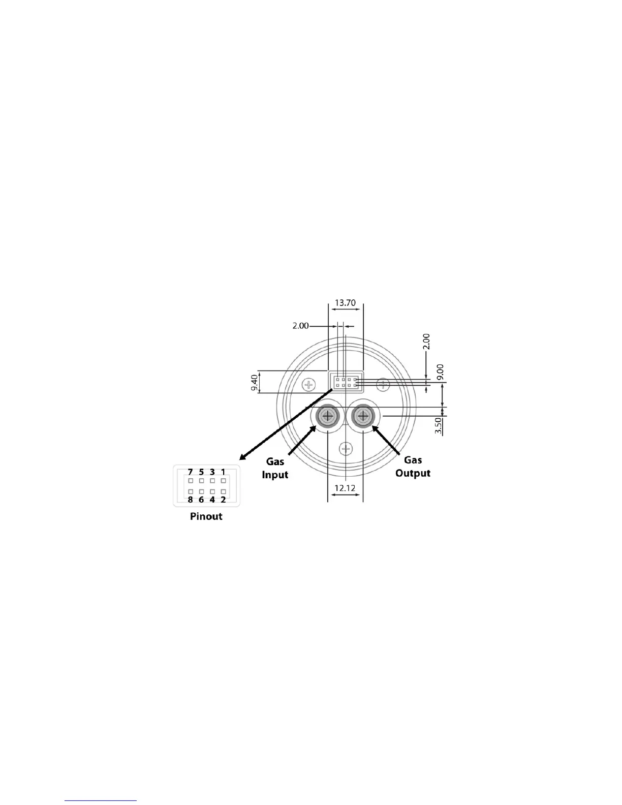
sensor module is operated. The following mechanical drawing
includes the sensor module interface connector’s pinout. The Ex
entity parameter of the equipment connected to the DigiPID must fit
the entity parameters of DigiPID according to intrinsically safe fitting
rules.
8-pin connector pinout configuration:
1: Power in
2: CS (Communication Select). Select (falling edge) to start
communication, deselect (rising edge) to stop communication.
3: Analog Signal Output
4: RXD
5: Open Drain
6: GND
7: Control Signal (Optional)
8: TXD
Note: Some external equipment requires no connection to pins 5 and 7.