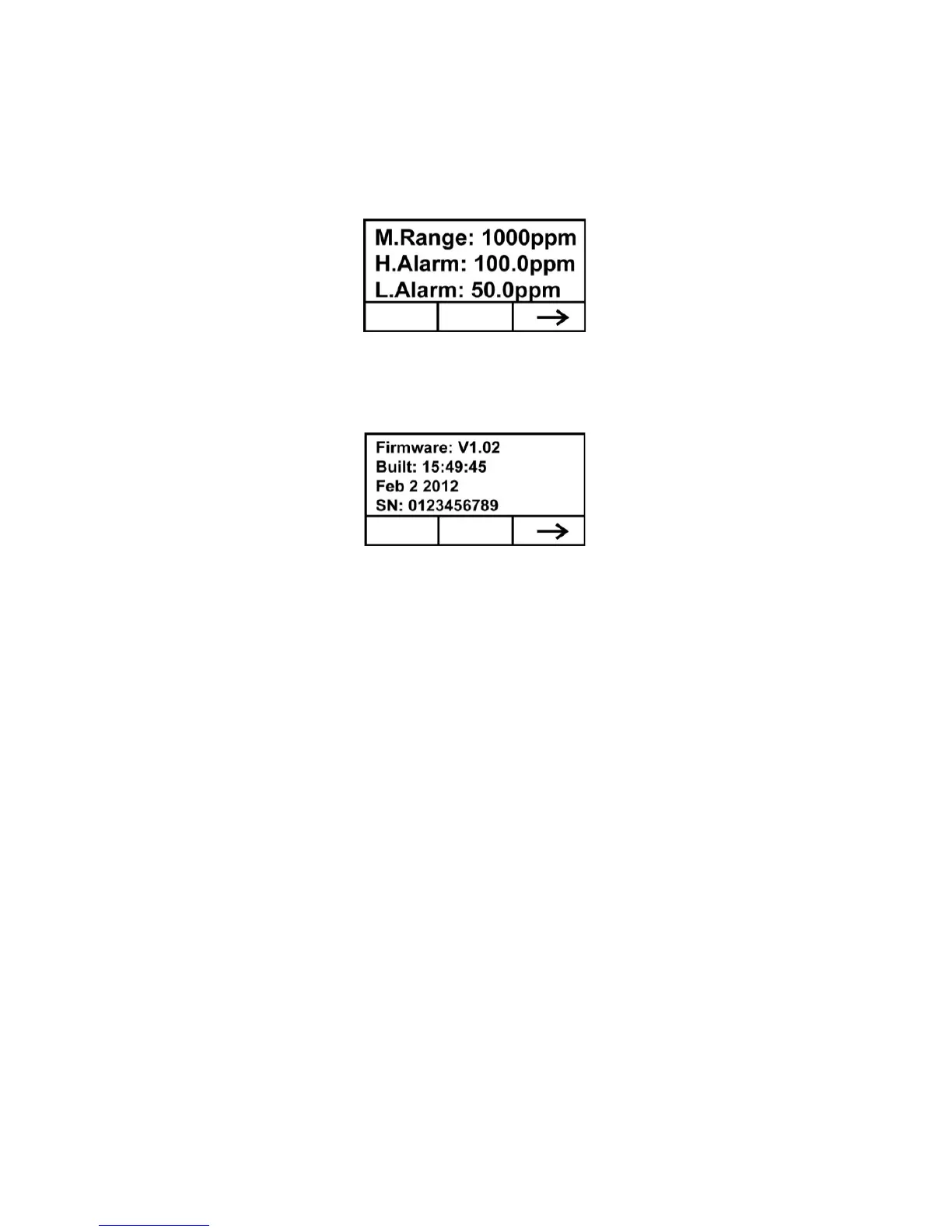
Press [-] to advance to the screen showing the measurement range
(M.Range) and high alarm (H.Alarm) and low alarm (L.Alarm)
values:
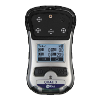
Press [-] to advance to the screen showing the firmware version and
build time and date, and the serial number of the instrument:
Press [-] to advance to the Analog Output Test screen.
The analog output test is primarily used when commissioning a
system. It ensures that the mA output at the sensor location is the
same as the input received on the system controller. Run the analog
test to make sure that the readings on the detector match the readings
on the controller.
The analog test uses a timed step function to output specific mA
values in sequence. The test starts at 4 mA, which typically
corresponds to 0 ppm output. The analog test then progresses in
increments of 2 mA (4, 6, 8, etc., all the way up to 20mA). The
corresponding sensor reading in ppm is shown on the unit’s LCD
display.