5. Instructions For Safe Use
It must be ensured that the supply voltage for RAEGuard 2 comply
with the Um input entity parameter. The 8-pin output interface
connector facilitates connection to intrinsically safe equipment, e.g.
sensors or modems. The connected devices must be protected by
intrinsically safety, ia, ib or ic for gases in group IIA, IIB or IIC.
The connected device must have entity parameters that comply with
general fitting rules for entity parameters with the output entity
parameters of the RAEGuard 2 interface. The DigiPID sensor can be
mounted on the on the RAEGuard 2 interface inside hazardous are in
powered condition. This constellation is called RAEGuard 2 PID.
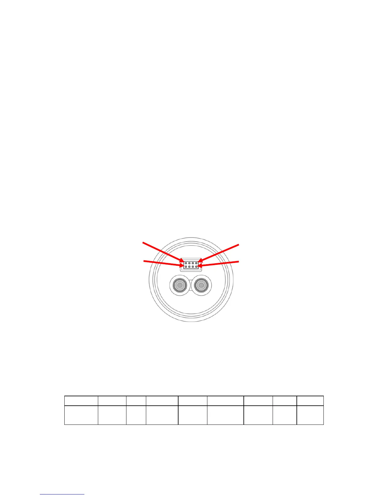
6. Connections And Ratings
Outline drawing of the interface:
Figure1
Output interface port definition:
The pin definition of the 8-pin output connector is given in the table
below: