ESP-2WIRE Controller
4
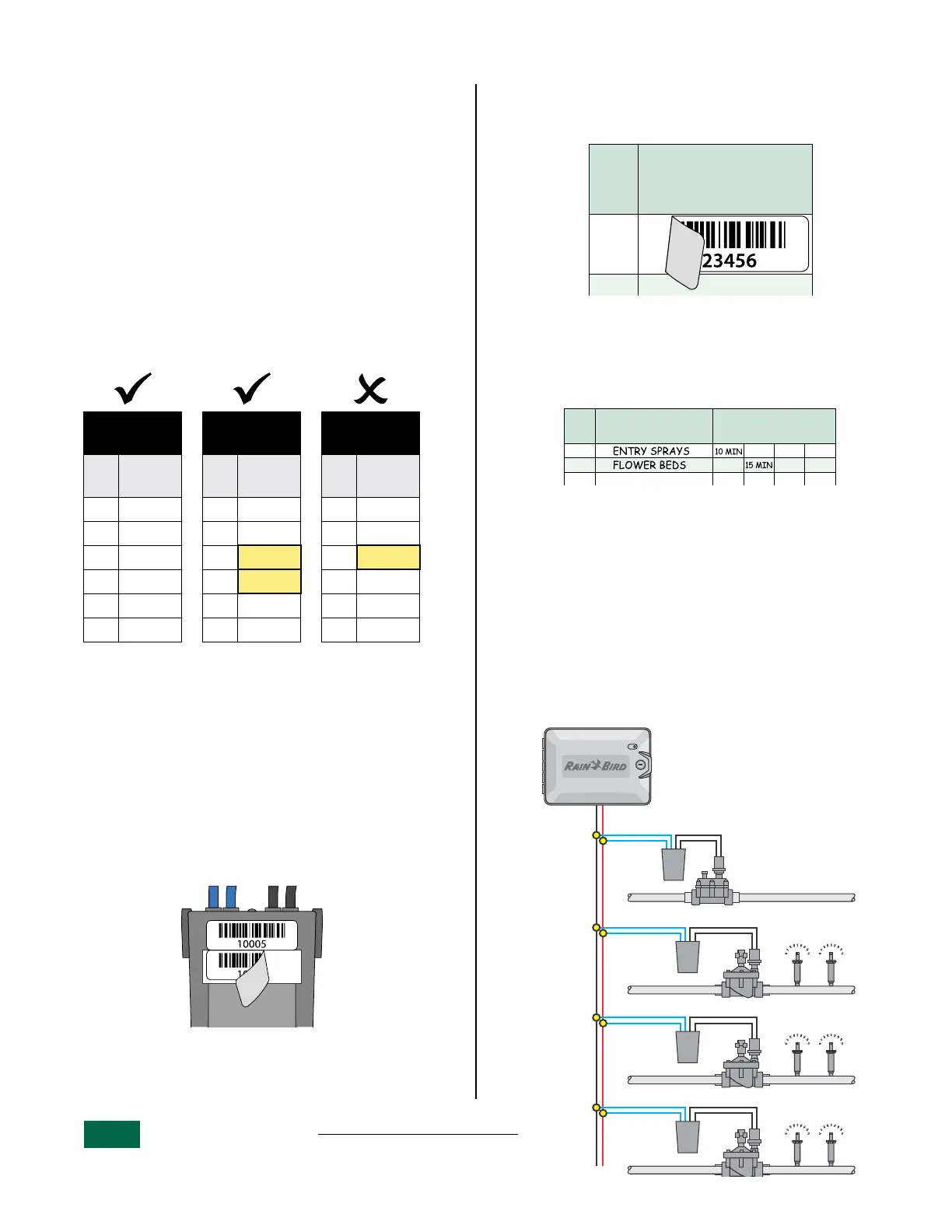
Sequential and Numerical Configuration
Decoder addresses don’t necessarily have to be in
sequential order as long as they’re in numerical
order.
It’s okay to skip numbers as long as lower numbers
come first in the sequence.
For example:
• Table 2.1 shows decoders in both sequential
and numerical order.
• Table 2.2 shows decoders out of sequence but
still in numerical order.
• Table 2.3 shows decoders incorrectly out of
numerical order.
Sequential
+ Numerical
Numerical
Numbers
out of order
Sta.
Decoder
Address
Sta.
Decoder
Address
Sta.
Decoder
Address
1 10001 1 10001 1 10001
2 10002 2 10002 2 10002
3 10003 3 10007 3 10015
4 10004 4 10008 4 10007
5 10005 5 10014 5 10008
6 10006... 6 10015... 6 10014
Table 2.1 Table 2.2 Table 2.3
B
NOTE: If decoders were installed out of order,
see “Change a Station’s Decoder Address” on
page 6.
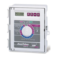
Place Decoder Address Labels
Apply the decoder barcode labels to the appropriate
fields on the Programming Chart that came with
your controller.
a
Carefully peel off the 2-Wire decoder barcode
label.
Remove Address Labels.
B
NOTE: Do not remove the label from the carri-
er still attached to the decoder.
b
Apply the barcode label to an available
row corresponding to a station on the
programming chart.
STATION
ESTACIÓN
No.
Address Labels
Etiquetas de identificación
Étiquettes d’adresse
1
Place Address Labels.
Fill Out The Programming Chart
Enter information in the appropriate fields on the
Programming Chart.
STATION
ESTACIÓN
Descripción/ Description
STATION
Description
Run Times
Tiempos de riego/ Heures d’arrosage
A BCD
1
2
3
Programming Chart Example.
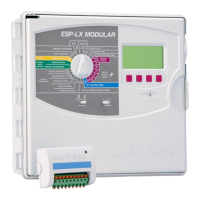
2-Wire Field Connections
Connect Decoders To The 2-Wire Path
a
Run a length of irrigation wire from the 2-Wire
Controller to the farthest valve location.
b
Connect the two blue wires from the 2W-1
Decoder to the two-wire path.
c
Connect the two black wires from the 2W-1
Decoder to a valve solenoid.
ESP-2WIRE Controller
typical Station/Valve
configuration.
MV
Station
1
Station
2
Station
3