ESP-ME3 Controller
4
EN
Installation
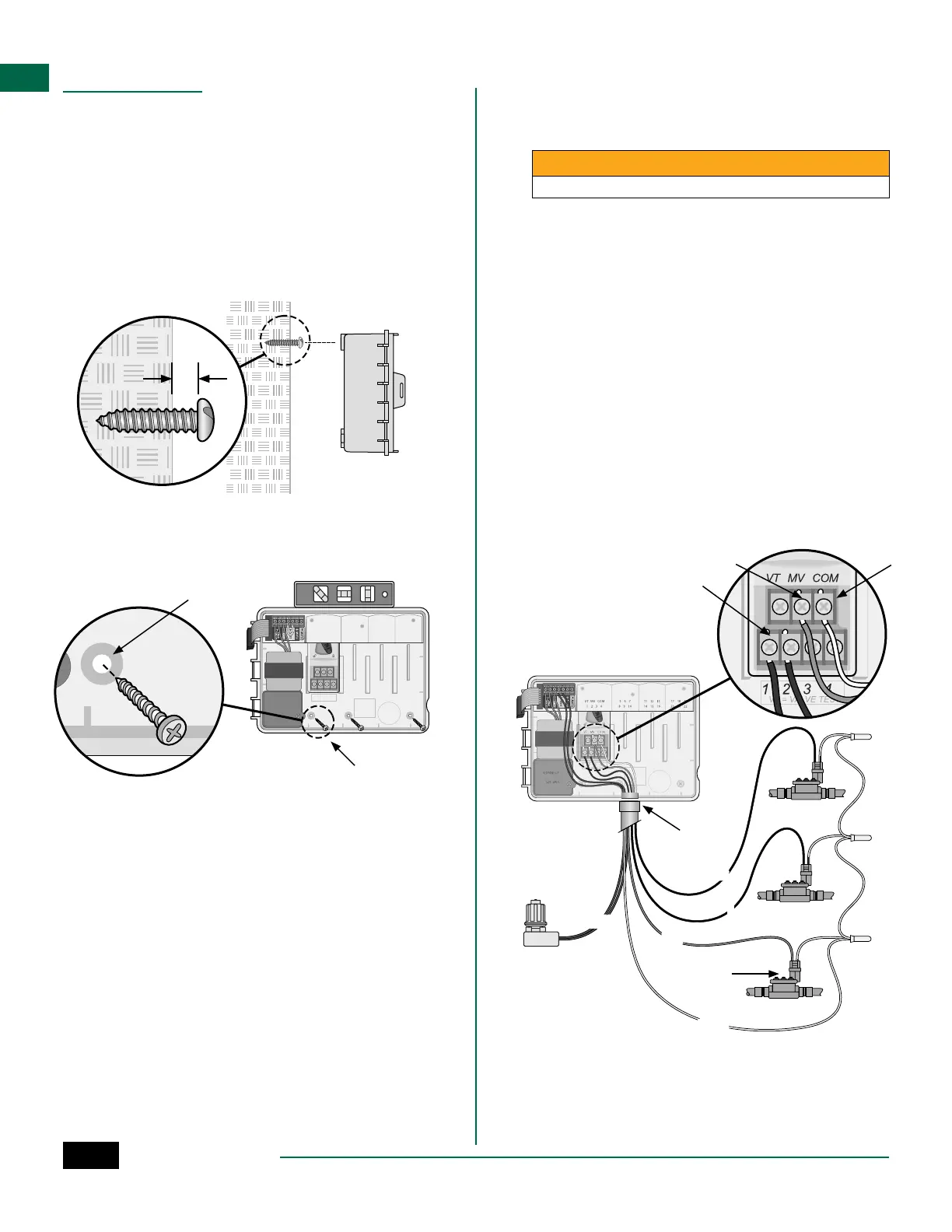
Mount Controller
NOTE: Choose a suitable mounting location close
to a 120VAC wall outlet.
A
Drive a mounting screw into the wall, leaving an
1/8 inch gap between the screw head and the
wall surface (use the supplied wall anchors if
necessary), as shown.
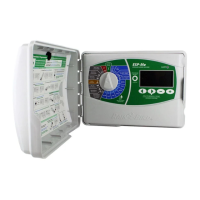
B
Locate the keyhole slot on back of the controller
unit and hang it securely on the mounting screw.
1/8 IN.
A
B
C
Open the front panel, and drive three additional
screws through the open holes inside the
controller and into the wall, as shown.
1234
VT VALV E TEST=
VT MV COM
VT MV COM567 11 12 13 17 18 19
1234 8910 14 15 16 20 21 22
CONNECT
120 VA C
C
A
B
MASTER
VALVE
COM
MV
1
2
SENS
E C
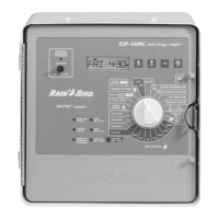
Connect Valves
A
Route all field wires through the opening at the
bottom or back of the unit. Attach conduit if
desired, as shown.
WARNING
Do not route valve wires through the same opening as power wires.
B
Connect one wire from each valve to the terminal
on the Base Module or Station Module that
corresponds to the desired station number (1-22).
C
Connect a field common wire to the COM
(common)terminal on the Base Module. Then
connect the remaining wire from each valve to
the field common wire, as shown.
D
To perform a Valve Test, connect the common wire
to the COM terminal and the power wire to the VT
terminal. This will immediately turn the valve ON.
Connect Master Valve (optional)
E
Connect a wire from the master valve to the MV
(master valve) terminal on the Base Module.
Then connect the remaining wire from the master
valve to the field common wire, as shown.