STARTING AND OPERATING 153
Wheel Alignment Mode
Before performing a wheel alignment, this mode
must
be enabled Ú page 216.
Protection Strategy
In order to “protect” the air suspension system, the
v
ehi
cle will disable load leveling as required
(suspension overloaded, battery charge low, etc.).
Load leveling will automatically resume as soon as
system operation requirements are met. See an
authorized dealer if system does not resume.
NOTE:
For towing with air suspension Ú page 196.
INSTRUMENT CLUSTER DISPLAY
M
ESSAGES
When the appropriate conditions exist, a message
will appear in the instrument cluster display
Ú page 104.
An audible chime will be heard whenever a system
e
rror
has been detected.
See an authorized dealer for system service if
norma
l operation does not resume.
OPERATION
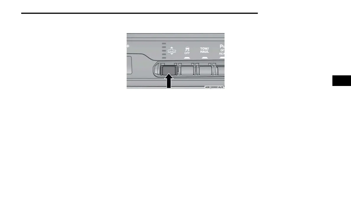
Air Suspension Switch
The indicator lamps 1 through 5 will illuminate to
show
the current position of the vehicle. Flashing
indicator lamps will show a position which the
system is working to achieve. When raising, if
multiple indicator lamps are flashing, the highest
flashing indicator lamp is the position the system is
working to achieve. When lowering, if multiple
indicators are flashing, the lowest solid indicator
lamp is the position the system is working to
achieve.
Pushing the height selector up once will move the
susp
ension one position higher from the current
position, assuming all conditions are met (i.e.,
ignition in ON/RUN position, engine running, speed
below threshold, etc.). The height selector switch
can be pushed up multiple times, each push will
raise the requested level by one position up to a
maximum position of OR2 or the highest position
allowed based on current conditions (i.e., vehicle
speed, etc.).
Pushing the height selector down once will move
the
suspension one position lower from the current
level, assuming all conditions are met (i.e., ignition
in ON/RUN position, engine running, doors closed,
speed below threshold, etc.). The height selector
switch can be pushed down multiple times, each
push will lower the requested level by one position
down to a minimum of Entry/Exit Mode or the
lowest position allowed based on current
conditions (i.e., vehicle speed, etc.).
Automatic height changes will occur based on
vehi
cle speed and the current vehicle height. The
indicator lamps and instrument cluster display
messages will operate the same for automatic
changes and user requested changes.
Off-Road 2 (OR2) – Indicator lamps 5, 4, 3,
2 and 1 will be illuminated when the vehicle is in
OR2.
Off-Road 1 (OR1) – Indicator lamps 5, 4, 3 and
2 will be illuminated when the vehicle is in OR1.
Normal Ride Height (NRH) – Indicator lamps 5,
4 and 3 will be illuminated when the vehicle is in
this position.
Aero Mode – Indicator lamps 5 and 4 will be illu-
minated when the vehicle is in this position.
4