Operating Manual 1505.3896.12 - 14 178
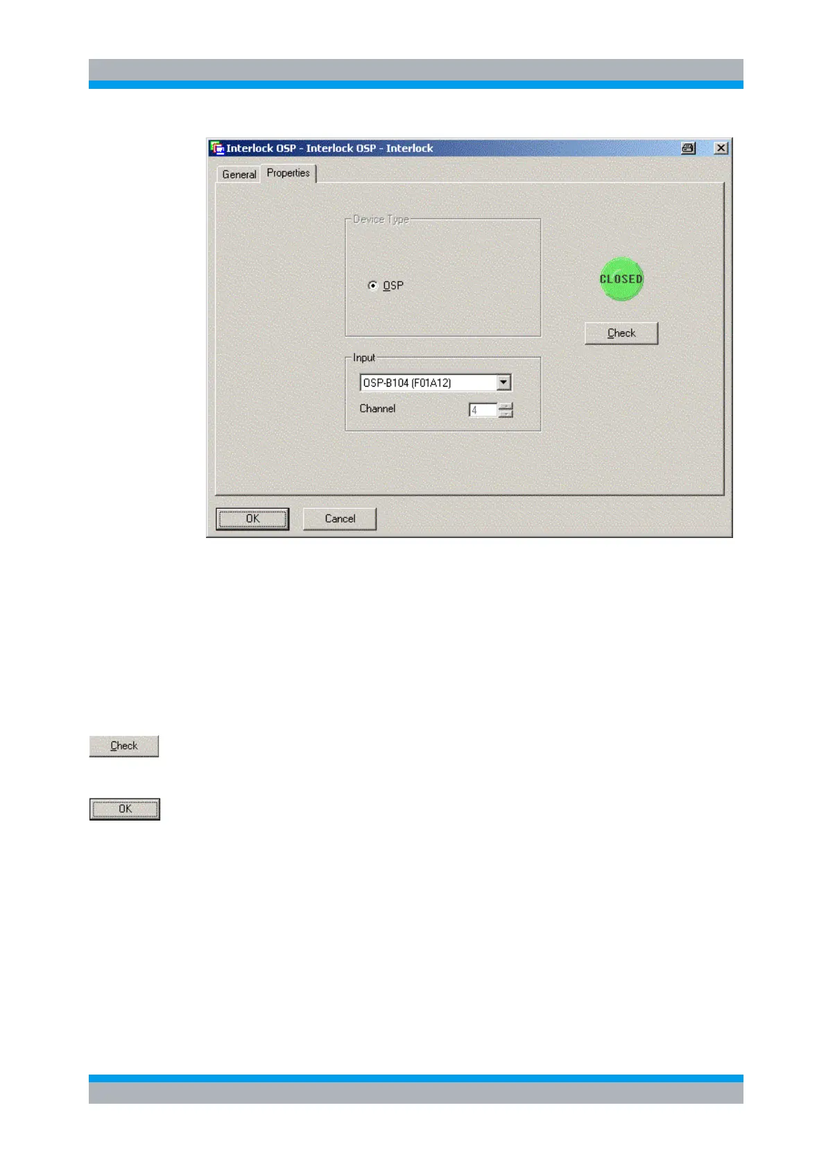
If the field Input gives you the choice to select one out of several modules of your R&S
OSP, you may select the one where the interlock loop is connected to. If the R&S OSP
is only equipped with one module, either R&S OSP-B103 or R&S OSP-B104, only this
module can be selected.
If the selected module is an R&S OSP-B103, there is free choice of the channel to be
used. Please select the channel as appropriate.
If the selected module is an R&S OSP-B104, there is a fixed relation to the input
channel. In this case the field Channel has no meaning. See chapter 9.2.4 for the
pinout at the connector.
Pressing the Check button will read the status of the interlock thus allowing you to
verify that the correct selection has been made. The interlock status is shown as a
green Closed or as a red Open indicator.
Press the OK button to store the actual property settings in R&S EMC32.