Instruction manual
RAVTD3000 - RAVTD3000HP
RAVTD3000NRC - RAVTD3000ATS
Code M0215 - rev.1.1
(11/2012)RAVAGLIOLI S.p.A.
RAVAGLIOLI S.p.A. - Via I° Maggio, n° 3 (Pontecchio Marconi)
Page 1/52
40037 Sasso Marconi (Bologna - Italy)
Tel. 051/ 67.81.511 – Fax 051/ 84.64.67 E-mail: rav@ravaglioli.com
CONTENTS
0 CAUTION ................................................................................................................................................ 3
0.1 Preliminary Safety Information ............................................................................................................ 3
1 INTENDED USE ..................................................................................................................................... 4
2 OPERATOR TRAINING ....................................................................................................................... 4
2.1 General Preventive Measures ............................................................................................................... 4
3 MACHINE COMPOSITION ................................................................................................................. 5
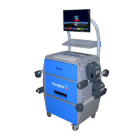
3.1 Cabinet of models RAVTD3000/ATS/NRC/HP .................................................................................. 5
3.2 Cabinet of models RAVTD3000 .......................................................................................................... 6
3.3 Managing PC ........................................................................................................................................ 7
3.4 MEASURING HEADS ........................................................................................................................ 7
3.4.1 Power/recharge cables for measuring heads .................................................................................................. 8
3.4.2 Measuring head keypads ................................................................................................................................. 9
3.4.3 LED indicating tolerance during adjustment .................................................................................................. 9
3.5 Clamps with target .............................................................................................................................. 10
3.6 Rotating Plates .................................................................................................................................... 11
3.6.1 Rotating Plates STDA124 ............................................................................................................................. 11
3.7 Pedal depressor ................................................................................................................................... 11
3.8 Steering lock ....................................................................................................................................... 11
4 SYSTEM FEATURES ........................................................................................................................... 12
4.1 Safety Devices .................................................................................................................................... 12
4.2 Measurement Range and Accuracy .................................................................................................... 12
4.3 Overall Dimensions ............................................................................................................................ 12
5 TRANSPORT AND INSTALLATION ............................................................................................... 13
5.1 Transport and unpacking .................................................................................................................... 13
5.2 Installation .......................................................................................................................................... 13
5.2.1 Power connections ........................................................................................................................................ 13
5.2.2 Cabinet mounting .......................................................................................................................................... 13
5.2.3 Clamp/Target Mounting ................................................................................................................................ 14
5.2.4 Mounting the measurement head unit supports ............................................................................................ 15
6 SWITCHING THE MACHINE ON AND OFF .................................................................................. 16
6.1 Switching the Machine On ................................................................................................................. 16
6.2 Switching the Machine Off ................................................................................................................. 16
7 MEASURING HEAD AUTOMATIC SWITCHING OFF ................................................................ 18
8 FLAT BATTERY INDICATION ......................................................................................................... 18
9 PROGRAMME CONFIGURATION .................................................................................................. 19
9.1 DATABASE Groups Configuration ................................................................................................... 20
10 VEHICLE DIAGNOSIS AND ADJUSTMENT ................................................................................. 22
10.1 Introduction Page ................................................................................................................................ 22
10.2 Preliminary Operations ....................................................................................................................... 23
10.2.1 Vehicle Check Preliminary Operations......................................................................................................... 23
10.2.2 Measurement Preliminary Operations .......................................................................................................... 23
10.3 Vehicle Make and Model Selection .................................................................................................... 25
10.4 Selected Vehicle Technical Specification Displaying ........................................................................ 27
10.5 Thrust Out-of-centre with Automatic Acquisition .............................................................................. 28
10.6 Measurement Preliminary Operations ................................................................................................ 30
10.7 Vehicle alignment / direct measurement operations ........................................................................... 31
10.8 Steering Procedure .............................................................................................................................. 32
10.9 Vehicle Diagnosis ............................................................................................................................... 33
10.10 Adjustment Preliminary Operations ................................................................................................... 34
 Loading...