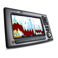
4.3a9xanda12xconnectionsoverview
Thea9xanda12xvariantMFDsincludethefollowing
connections.
1.Sonartransducer(a97anda127)/DownVision
TM
transducer(a98anda128)
2.SeaTalk
ng
3.Network1(RayNet)
4.Network2(RayNet)
5.Poweranddata
6.GA150antenna
Connectorandcableprotectivecaps
Unusedconnectorsanddisconnectedcablesshould
beadequatelyprotectedagainstdamage.
Important:
Therearconnectorsonyourproductarettedwith
protectivecapswhichshouldbesecurelytted
overanyconnectorsthatarenotgoingtobeused
/connected.
Ifanycablesaretobeleftdisconnectedthen,
ifavailableusethecablesprotectivecapor
insulationtapetoprotectthecableconnector.
4.43–pinpowerconnection
ThedetailsbelowapplytoMFDsthathavea3–pin
powercable.
RefertotheConnectionsOverviewsectionto
establishthepowerconnectionforyourMFD.
1.MFD
2.3–pinpowercable
3.Connectiontopowersupply
4.Redcable(positive)
5.Ground(drain)wire
6.Blackcable(negative)
Warning:Powersupplyvoltage
TheMFDslistedbeloware12Vdconly
products:
•a6x/a7x
•e7/e7D
DoNOTconnecttheseproductstoa24
Vpowersupply.
In-linefuseandthermalbreakerratings
Thefollowingin-linefuseandthermalbreakerratings
applytoyourproduct:
In-linefuseratingThermalbreakerrating
5A
3A(ifonlyconnectingone
device)
Note:
•Thesuitablefuseratingforthethermalbreaker
isdependentonthenumberofdevicesyouare
connecting.Ifindoubtconsultanauthorized
Raymarinedealer.
•Yourproduct’spowercablemayhaveatted
in-linefuse,ifnotthenyoumustaddanin-line
fuse/breakertothepositivewireofyour
productspowerconnection.
38aSeries/cSeries/eSeriesinstallationinstructions

 Loading...


