Chapter 3
Input & Output Connections
RBH Access Technologies Inc. Integra32
™
Hardware Guide
29
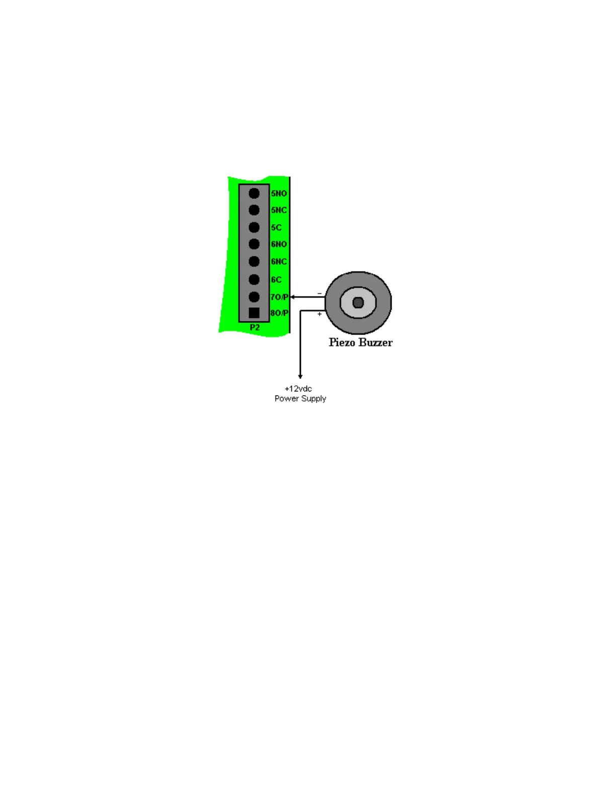
Electronic Output Connection Diagram
The electronic outputs are capable of switching up to 100ma to ground.
Switching Inductive Devices (Locks, Bells)
Exercise caution when switching an inductive load. Inductive devices include external
relay, solenoids, bells, and door locks. All of these devices generate extremely high voltage
spikes (several thousand volts) when power is applied or removed and possible disruption of
the operation could occur if this interference gets on to the electronic circuit board.
This interference can be suppressed by placing a diode (1N4004 or similar) across the lock
or other inductive device being switched. Connect the diode cathode (end with band) to the
positive terminal and the other end to the negative terminal. The diode must be placed at
the device being switched and not at the controller.