3333
ITALIANOENGLISH
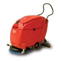
WASHER-DRIER MAINTENANCE
(FIG.4)
ATTENTION!
ENSURE THAT THE WASHER-DRIER IS CUT OFF FROM ANY VOLTAGE BEFORE PERFORMING ANY MAINTENANCE OPERATIONS. PROCEED AS FOLLOWS:
- Stop brush and suction rotation by pressing the relative symbols located on the start-up panel. sui
- for battery-operated machines with the “auto-stop” system, wait a few seconds before working on the washer-drier
- for battery-operated machines with “start-up keys”, turn the key to the “0” position and then remove it.
- for “230V.AC cable-operated” machines, disconnect the cable from the power outlet.
Brush replacement
- Tilt the washer-drier to lift the front part (brush base) and keep it tilted by lifting wheel 1.
- Turn the brush 2 counter-clockwise A completely to unlock and remove it.
- Insert the new brush on the base and turn it clockwise B to lock it.
Replacing the drying edge or substituting the squeegee blade
If the front 3 and back 4 squeegee blades are no longer drying entirely, replace the drying edge. Substitute the blade if the edge is
completely worn.
Front blade
- lift the squeegee via lever 5
- dismantle the squeegee.
- remove the six knobs 6 holding down the cross piece 7 on the blade
- remove the blade, turn it and utilise new edge. Replace it if all 4 edges are completely worn.
- Reassemble
Back blade
If the back blade 4 of the squeegee is no longer drying entirely, replace the drying edge. Substitute the blade if the edging is completely worn.
- lift the squeegee via lever 5
- dismantle the squeegee.
- remove the six knobs 6 holding down the cross piece 7 on the blade
- remove the six screws 8
- remove the cross-piece 9
- remove the blade, turn it and utilise new edging. Replace it if all 4 edges are completely worn.
- Reassemble.
BATTERY CHARGING (WITH SUPPLIED BUILT-IN BATTERY CHARGER)
(FIG.5)
ATTENTION!
CAREFULLY READ THE BATTERY CHARGER USER AND MAINTENANCE MANUAL BEFORE CHARGING BATTERIES
THE ELECTRICAL SYSTEM FOR BATTERY-OPERATED MACHINES MUST NOT BE POWERED. PROCEED AS FOLLOWS:
- Stop brush rotation and suction by pressing the relative symbols located on the start-up panel.
- for battery-operated machines with “auto-stop systems” do not utilise the machine for a few seconds
- for battery-operated machines with “start-up keys”, turn the key to the “0” position and then remove it.
ATTENTION!
NEVER ALLOW BATTERIES TO RUN DOWN COMPLETELY EVEN IF THE MACHINE IS NOT BEING UTILISED. REMOVE THE RECOVERY TANK
AND PERFORM CHARGING IN A COVERED AND WELL-VENTILATED AREA.
D
O NOT USE OPEN FLAMES OR SMOKE NEAR BATTERIES.
TAKE CARE WITH LIQUID AS IT IS CORROSIVE.
DO NOT PRODUCE ANY SPARKS NEAR BATTERIES.
BATTERY GASES ARE EXPLOSIVE; DO NOT PROVOKE SHORT-CIRCUITS OR INVERT THEIR POLARITY.
Battery charging status is signalled by LEDs 1 located on the control panel. When the batteries begin to lose power, the LEDs pass to:
Green= batteries charged, controls are active > Yellow= batteries semi-charged, controls are active > Red (fi xed)= Batteries run down, brush output and
electrovalve disabled. > Red (fl ashing)= Batteries run down, all controls disabled.
Utilise the battery charger 2 to re-charge batteries.
Connect the plug 3 of the battery charger to the power outlet. The battery charger will fi rst perform a battery voltage test; if the test is positive, after a second
battery charging will begin signalled by a red LED 4 located on the battery charger.
The LEDs 5 indicate the re-charging phases:
RED = INITIAL CHARGING PHASE, YELLOW= INTERMEDIATE PHASE, GREEN= FINAL PHASE AND CHARGING STOP, THE BATTERY IS READY.
ATTENTION!
WASHER-DRIER ELECTRICAL CONTROLS AND SYSTEM SHALL BE EXCLUDED DURING BATTERY CHARGING PHASES FOR SAFETY PURPOSES.
ATTENTION!
IF
GEL OR LEAD OR OTHERS BATTERIES HAVE BEEN INSERTED IN THE WASHER-DRIER, PERFORM THE SPECIFIC SETTINGS ON THE TWO “DIP SWITCHES” 6 OF THE
BATTERY CHARGER. “SEE FIG. 5 FOR SETTINGS . THE SETTINGS MUST BE DONE WHEN THE BATTERY CHARGER IS SWITCHED OFF.