2727
ITALIANOENGLISH
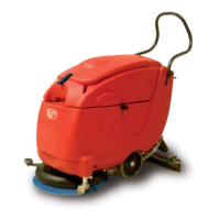
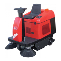
CONTROLS AND COMPONENTS
(FIG.1/A-B-C)
1) Brush control button
Activates and deactivates the electrovalve for releasing water onto the brush and control of the electrical motor for brush rotation.
ATTENTION! BRUSH ROTATION STOP.
THE CONTROL FIRST DEACTIVATES THE ELECTROVALVE, AND THEN BRUSH ROTATION AFTER 4 SECONDS, THUS ALLOWING DRYING
PHASE COMPLETION.
2) Suction control button
Suction motor control.
ATTENTION! BUTTONS 1 AND 2 (FIG.1/A) CONTROL “BRUSH” AND “SUCTION”.
PRESSING ONCE ON THE SELECTED BUTTON POWERS THE SYSTEM, “SEE WASHER-DRIER START-UP AND
USE.”
3) Battery charge status indicator
Indicates Battery charge status “see BATTERY CHARGING”.
4) Electronic board brush motor protection
(for 230V.AC cable-operated machines)
The electronic board activates and cuts off power to the brush motor to safeguard it when a level of absorption which is too high is reached,
caused by improper use of the machine when the brush is stuck, locked or the (230V) power supply is interrupted suddenly.
If these problems occur, proceed as follows:
Check the brush and possibly unblock it . Push the control brush rotation button (1 Fig.1/A) to restore the motor functioning.
5) Light (red) for inserted power cable
(for 230V.AC cable-operated machines)
This light indicates that the cable power plug has been inserted in a power electrical outlet and the machine has thus been powered.
6) Squeegee raising/lowering lever
Used to raise or lower the squeegee. A= Raising, B= Lowering
7) Squeegee
Used to suction dirty solution and dry the brush-cleaned fl oor.
8) Water drainage tube
Used to drain the tank (recovery) with the dirty solution.
9) Solution tank fi lling opening
Used to fi ll the machine with a cleaning solution (water+detergent)
10) Battery bay (for battery-operated machines)
Where batteries are installed, see “BATTERY INSTALLATION”
11) Batteries (for battery-operated machines)
See “BATTERY INSTALLATION” AND WIRING DIAGRAM (FIG.6)”.
12) 230V.AC cable (for electrically-operated machines)
See “PRECAUTIONS FOR AC POWERED MACHINES” + “WIRING DIAGRAM (FIG.7)”
13) Disc brush
Used to clean fl ooring areas.
14) Brush control electric motor
Controls brush rotation.
15) Clean water (solution) open/close valve
Opens, regulates and closes cleaning solution on the brush. See “
“WASHER-DRIER START-UP AND USE” – opening and regulation of cleaning solution on the brush”
16) Suction motor
this motor’s function is to suction up liquids gathered by squeegee operation