81
1
2
4 3
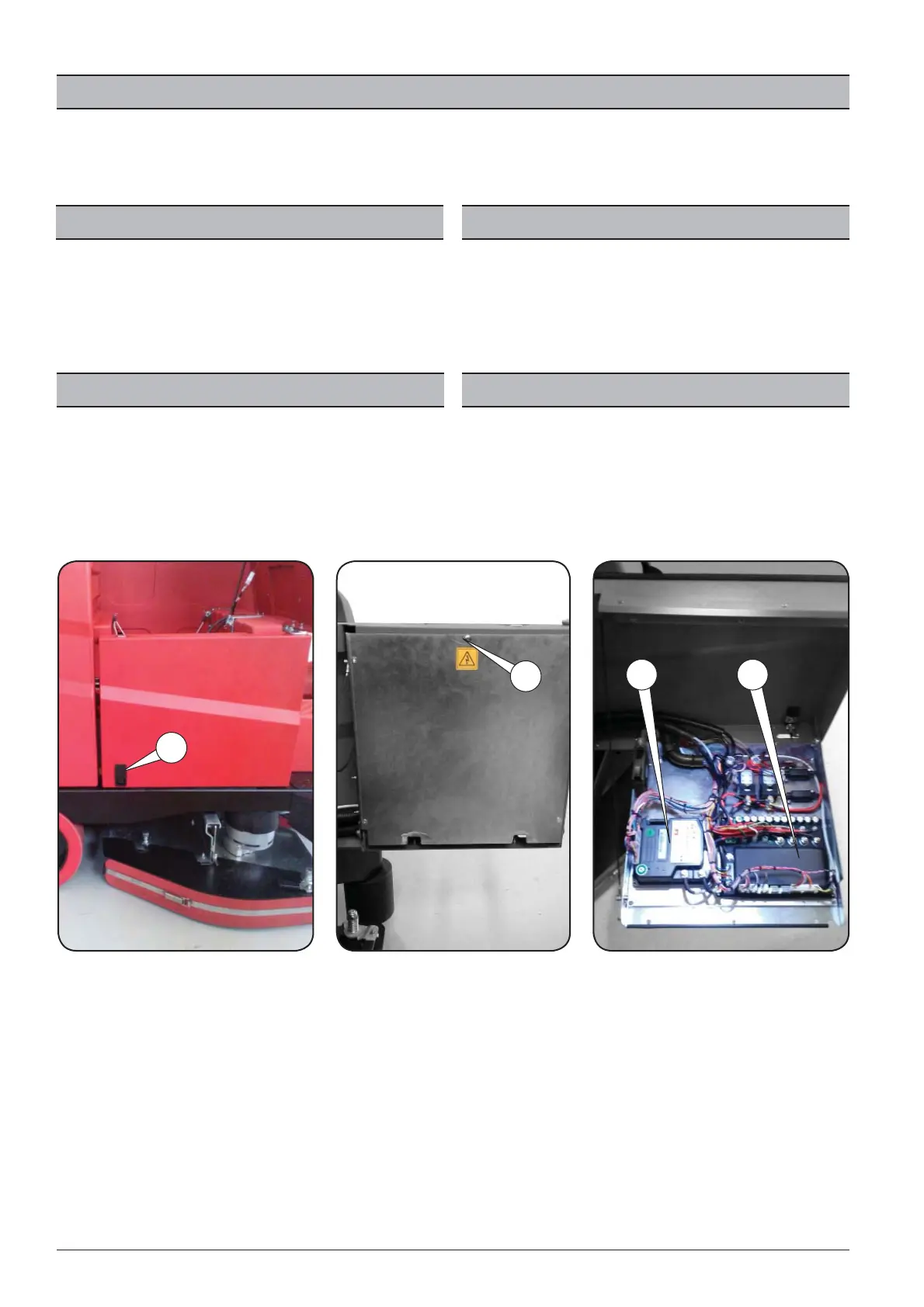
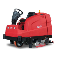
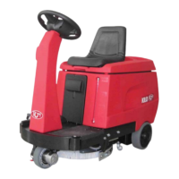
IMPIANTO ELETTRICO
Per accedere all’impianto elettrico della macchina, aprire lo sportello laterale 1 svitare le viti 2 . L’impianto elettrico è composto da un inverter controllo trazione 4 e
una scheda controllo elettronico 3 per le funzioni della macchina e vari componenti elettrici descritti nel capitolo “SCHEMA ELETTRICO”. In caso di anomalia/e o mal-
funzionamento della macchina, l’ inverter o la scheda funzioni visualizzeranno l’allarme sul display con una sigla. ( vedere tabella“ALLARMI”).
ELECTRICAL SYSTEM
To access the electrical system of the machine, open side door 1 unscrew screws
2. The electrical system consists of a traction control inverter 4 and an electronic
control board 3 for the machine functions and the various electrical components
described in the "WIRING DIAGRAM" chapter. In the event of a machine fault and/
or malfunction, the inverter or the function board will show the alarm on the
display with an acronym. (see "ALARMS" table).
SISTEMA ELÉCTRICO
Para acceder al sistema eléctrico de la máquina abra la puerta lateral 1 y desen-
rosque los tornillos. El sistema eléctrico está compuesto por inversor de control
de la tracción 4 y por una tarjeta de control electrónico 3 para las funciones de
la máquina y de los diferentes componentes eléctricos descritos en el capítulo
“ESQUEMA ELÉCTRICO”. En caso de anomalías y/o malos funcionamientos de la
máquina, el inversor o la tarjeta de funciones visualizarán la alarma en la pantalla
con una sigla. (vea la tabla “ALARMAS”).
INSTALLATION ÉLECTRIQUE
Pour avoir accès à l'installation électrique de la machine, ouvrir le volet latéral 1
et dévisser la vis 2. L’installation électrique se compose d’un inverseur de contrôle
traction 4 et une carte de contrôle électronique 3 pour les fonctions de la machi-
ne et di érents composants électriques décrits au chapitre “SCHÉMA ÉLECTRIQ-
UE”. En cas d’anomalie et/ou de dysfonctionnement de la machine, l’inverseur ou
la carte des fonctions visualiseront l’alarme sur l’écran avec un sigle. (voir tableau
“ALARMES”)
ELEKTRISCH SYSTEEM
Open de zijdeur 1 en schroef de twee schroeven 2 los om bij het elektrische sy-
steem van de machine te komen. Het elektrische systeem bestaat uit een inverter
voor controle van de tractie 4 en een elektronische besturingskaart 3 voor de
functies van de machine en verschillende elektrische componenten beschreven
in het hoofdstuk “ELEKTRISCHE SCHEMA”. In geval van storing(en) of slechte wer-
king van de machine geven de inverter of de kaart van de functies het alarm op
het display aan de hand van een code weer. (zie tabel “ALARMEN”).