reachrobotics.com
info@reachrobotics.com | +61 (2) 9519 7651
16
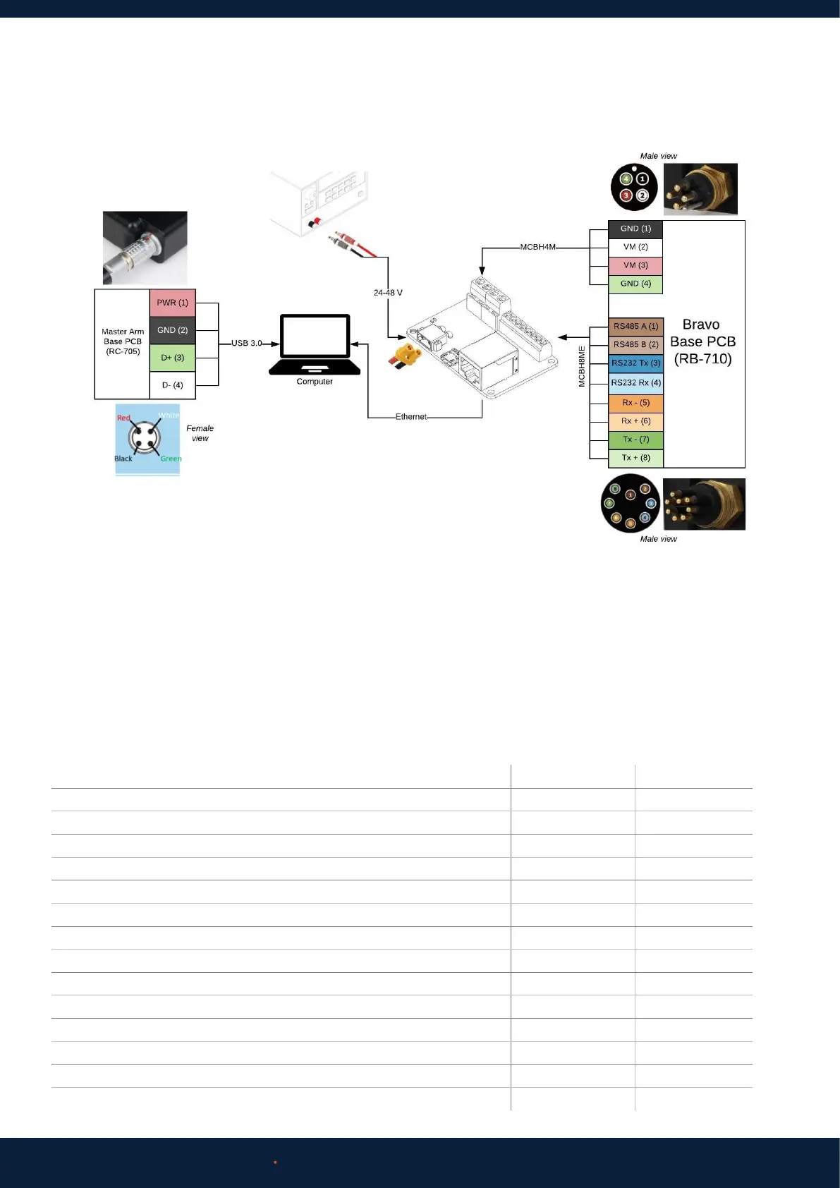
4.3 INTEGRATION ELECTRICAL DIAGRAM
For more detailed information to assist with research and low-level control/autonomy applications, please contact
Reach Robotics regarding our Reach System Research Data Pack.
Reach Bravo manipulators can be controlled by using the Reach Control Graphical User Interface, an external input such as a
Gamepad or Reach Robotics Master Arm, or by implementing the Reach Control Communication Protocol for custom control
setups.
5 CONTROL OPTIONS
5.1 REACH CONTROL
Reach Control is available in two packages, Reach Control Lite (RC-1000) and Reach Control Pro (RC-2000). A comparison of
these packages are as follows:
Feature RC Lite RC Pro
Communication over TCP/IP, serial, or UDP Ye s Ye s
Diagnostics and status monitoring Ye s Ye s
Customisable limits of position, velocity, and force Ye s Ye s
Basic Kinematics for Obstacle Avoidance Ye s Ye s
Workspace Obstacle Avoidance Ye s Ye s
Number of Obstacles 1 8
Advanced Kinematics Engine Ye s Ye s
Cartesian (XYZ) End-Eector Control No Yes
Eye-Ball Control (move arm with respect to tool/sensor orientation) No Yes
Crack and Feature Measurement Tool No Yes
Data Logging Tool No Yes
Custom Probe Configuration No Yes
End-Eector Tool Configuration No Yes
Position Presets 2 4
 Loading...