4” Standard Pump Installation, Operation & Service Manual Conduit Box Wiring
20
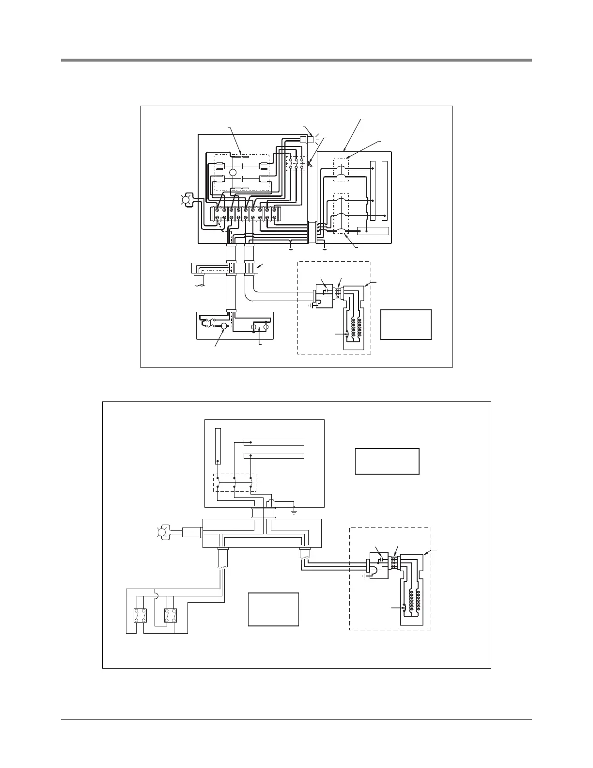
Figure 15. 230 Vac Remote Control Box with 110 Vac coil - Model 880-041-5
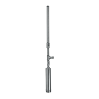
Figure 16. Suggested Wiring Diagram without Optional Control Box
Dispenser
lights
External
pilot light
(115 volts)
25 watt max.
Optional other
dispenser
(max. total of
6 dispensers)
EXT
PILOT
LIGHT
15A-3P switched
neutral breaker
1 phase, 3 wire
15A-2P switched
neutral breaker
Make ground
connection in
accordance with
local codes
Load center
208 or 230 volt
3 P.S.T.
toggle
switch
Pilot light
Line starter
Dispenser
Wiring
trough
Optional solenoid valve
(76 volt amps. max
N
L2 L1
S1 S2 M2 M1 N L1 L2
153-4.eps
Electrical
interlock
Internal
overload
protector
Continuous
duty capacitor
Extractable
packer
Junction box
in manifold
Motor
STP
R
B
O
G
153-5.eps
P
Load center 230 V, 1 Phase, 3 Wire
115 volt ext. pilot
light by contractor
2 pole dispenser switches
15 amp, 3 pole switch
(N.E.C. requires disconnect
break all wires to dispensers)
N
Make ground
connection in
accordance with
local codes
Dispenser lighting
from separate circuit
Wiring
trough
Electrical
interlock
Internal
overload
protector
Continuous
duty capacitor
Extractable
packer
Junction box
in manifold
Motor
STP
R
B
O