13
Installation
Attaching the UMP
Table 6 lists the applicable UMPs for each packer/manifold.
The UMP is identified by the model number marked on the shell. The packer/manifold assembly with attached
piping is identified by the catalog number on the capacitor cover nameplate. The catalog number will be followed
by T1, T2, T3, or T4 on adjustable length pumps or a four-digit number indicating the original pump length in feet
and inches (a 9 ft. 6 inch [2896 mm] pump would have 0906 after the model number.
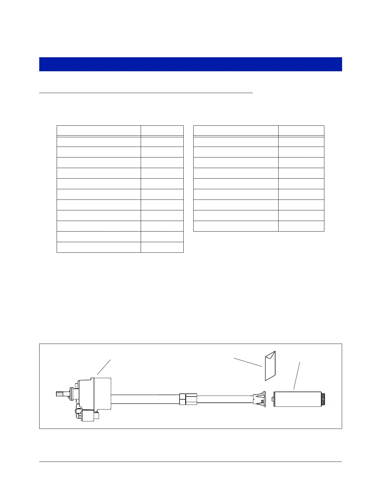
The attachment hardware kit to be used to connect the UMP to the Packer/Manifold assembly piping consists of
four Grade 5, 5/16 -18 x 1” socket head cap screws, four 5/16 spring lock washers and one discharge head
gasket. It is identified by the kit number (144-328-4) marked on the bag (see Figure 6).
NOTE: Suggested tools (non-sparking) include a 3/4'' wrench, pipe wrench, 1/4” allen wrench, 9/16” wrench,
screw driver, wire cutter and wire stripper.
Figure 6. Packer/manifold with piping attaching to UMP
Table 6.- Applicable UMPs for 4” Standard Packer/Manifolds
Packer/Manifold UMP Packer/Manifold UMP
AGP33R1 AGUMP33R1 P150S3-3 UMP150S3-3
P33R1 UMP33R1 X4AGP150S3 X4AGUMP150S3
AGP75S1 AGUMP75S1 X4P150S3 X4UMP150S3
P75S1 UMP75S1 AGP75S17-3 AGUMP75S17-3
AGP150S1 AGUMP150S1 P75S17-3 UMP75S17-3
P150S1 UMP150S1 AGP150S17-3 AGUMP15017-3
X3AGP150S1 X3AGUMP150S1 P150S17-3 UMP15017-3
X3P150S1 X3UMP150S1 X4AGP150S17 X4AGUMP150S17
AGP75S3-3 AGUMP75S3-3 X4P150S17 X4UMP150S17
P75S3-3 UMP75S3-3
AGP150S3-3 AGUMP150S3-3
rj\153\fig5.eps
Packer/Manifold
with piping
Kit (144-328-4) UMP