4” Standard Pump Installation, Operation & Service Manual Wiring Single-Phase Tandem Pumps
25
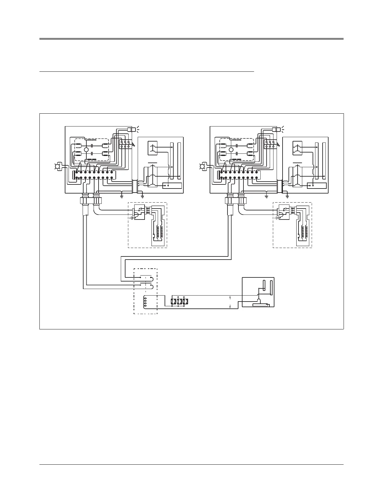
Wiring Single-Phase Tandem Pumps
Figure 22 shows the wiring allowing both STPs to operate simultaneously with any combination of dispensers
turned on. To operate individually, the appropriate toggle switch, located externally on the side of the control box
can be turned off manually.
Figure 22. Suggested Wiring for Tandem Pumps
P
EXT
PILOT
LIGHT
S1 S2 M2 M1 N L1 L2
P
EXT
PILOT
LIGHT
S1 S2 M2 M1 N L1 L2
S1
S1
L1 L2
N
S2
S2
110-350V
Dispenser Sw.
115 volt relay
Allen Bradley
700-C201
L1 L2
N
153-11.eps
Motor
STP
Motor
STP