4” Standard Pump Installation, Operation & Service Manual Installing a Replacement Extractable Pump
37
Installing a Replacement Extractable Pump
DANGER! Always disconnect, lock out, and tag the power before starting to service the pump.
When servicing unit use non-sparking tools and use caution when removing or installing equipment to
avoid generating a spark.
IF FIXED LENGTH, SKIP TO STEP 9.
1. If a ball valve is installed down line from the pump, close it.
2. Remove existing Red Jacket pump - see “Removing the Pump” on page 32.
NOTE: Confirm length of pump prior to installation.
CAUTION! Do not damage the surface above the discharge port. The o-ring below the leak detector port seals
on this surface.
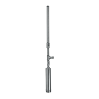
3. Attach the UMP (see “Attaching the UMP” on page 13.
4. Measure the distance from the bottom of the tank to the sealing surface on the manifold.
5. Uncoil pigtail and lay flat so it will feed into the packer without knotting or kinking.
6. Loosen the clinch assembly starting by unscrewing the set screw in the side of locking nut, then backing off
the locking nut (see Figure 10 on page 16).
NOTE: A slight twisting of the UMP will loosen the seals and facilitate adjusting it to the correct length.
WARNING! Do not rotate piping beyond 1/4 turn.
7. Pull the UMP end until the distance between the packer o-ring seal and the bottom of the UMP is 5 inches
(125 mm) (14 inches [356 mm] for floating suction) shorter than the distance measured in Step 4.
NOTE: If UMP is equipped with floating suction adapter, see “Recommended Floating Suction Installation”
on page 6.
Take care not to damage the pigtail. If pump is to be adjusted shorter, tension must be kept on the pigtail to
eliminate kinking.
8. Tighten the column pipe locking nut and torque to 150 ft-lb (200 N•m), then torque the set screw to 30 - 35
in-lb (3.5 - 4 N•m).
9. Attach tubing to barbed fitting, secure with clamp.
NOTE: Return line should be installed on every application to reduce nuisance trips of electronic tank moni-
toring.
10. Lay the siphon return line tubing beside the column pipe. Stop 1 - 3 inches (25 - 76 mm) above the discharge
head.
11. Secure the siphon return line tubing to the column pipe with tie straps. Locate the tie straps approximately 6
inches (152 mm) from packer, 6 inches from the discharge head, and in the middle of the tubing.
WARNING! For fixed length pumps:
If removed, install eyebolt plug, using an adequate amount of fresh, UL classified for petroleum, non-setting
thread sealant and torque to 50 ft-lbs (70 N•m). Confirm that the lifting eyebolt is properly torqued to 10 ft-
lbs (13.6 N•m) with a minimum of 6 full threads installed. Occasionally, eyebolts are removed after pump in-
stallation and corrosion may occur in the threaded areas of the wiring compartment cover (eyebolt plug) and
the eyebolt. If corrosion has occurred, the cover and eyebolt should be replaced.
Utilize the lifting eyebolt to suspend the pump vertically and then install the pump into the manibold per
Step 18.