4” Standard Pump Installation, Operation & Service Manual Installing the Pump
16
3. Uncoil the pigtail and lay it flat so it will feed into the packer without knotting or kinking.
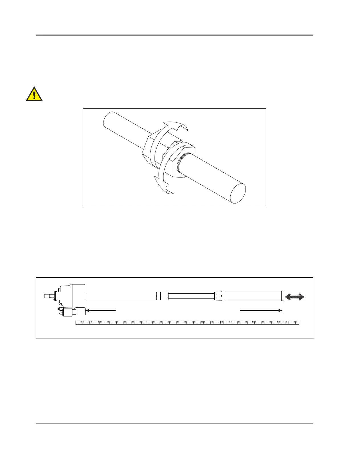
4. Loosen the clinch assembly starting by unscrewing the set screw in the side of locking nut, then backing off
the locking nut (see Figure 10).
NOTE: A slight twisting of the UMP will loosen the seals and facilitate adjusting it to the correct length.
WARNING! Do not rotate piping beyond 1/4 turn.
Figure 10. Loosening Locking Nut
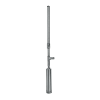
5. Referencing Figure 11, pull the UMP end until the distance between the bottom of the manifold and the
bottom of the UMP is 5 inches (125 mm) (15 inches [381 mm] for floating suction) shorter than the distance
measured in Step 2.
NOTE: If UMP is equipped with floating suction adapter, see section entitled “Recommended Floating Suc-
tion Installation” on page 6.
Figure 11. Adjusting pump length
NOTE: Take care not to damage the pigtail. If pump is to be adjusted shorter, tension must be kept on pigtail
to eliminate kinking.
6. Tighten the column pipe locking nut and torque to 150 ft-lb. (200 N•m) minimum, then torque the setup screw
in the locking nut to 30 - 35 in. lb. (3.5 - 4 N•m).
NOTE: Return line should be installed on every application to reduce nuisance trips of electronic tank moni-
toring.
7. Attach tubing to barbed fitting, secure with clamp.
rjpumps/fig8.eps
1/4 turn maximum on piping
rj\153\fig11.eps
5'' (125mm) shorter than Step 2 measurement