4” Standard Pump Installation, Operation & Service Manual Wiring Three Phase Tandem Pumps
26
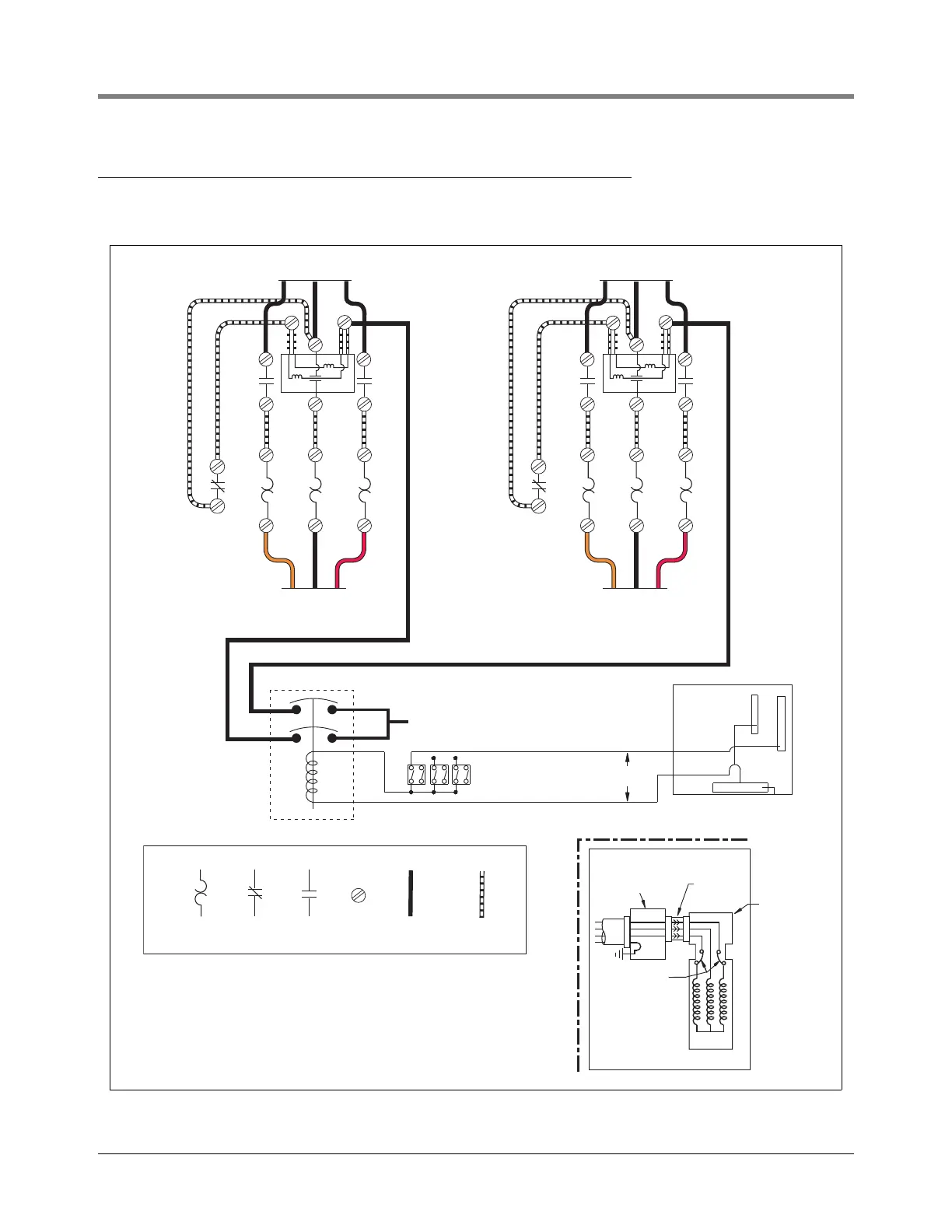
Wiring Three Phase Tandem Pumps
Figure 23 shows the wiring schematic which allows both three phase STPs to operate simultaneously with any
combination of dispensers turned on.
Figure 23. Suggested Wiring For Three Phase Tandem Pumps
230V
Dispenser Sw.
153/3ptndmwir.eps
Orange RedBlack
T1
L1
L1 L2 L3
L2
L3
X2
T2 T3
To STP by Installer
(see diagram below)
To STP by Installer
(see diagram below)
To Power Supply by Installer To Power Supply by Installer
COIL
3 421
3
Orange RedBlack
T1
L1
L1 L2 L3
L2
L3
X2
T2 T3
COIL
3 421
3
2 Pole
Relay
Neutral of Power Supply
LEGEND
Overload
heater
Normally
closed
contact
Normally
open
contact
Screw
terminal
Wire added
by installer
Wire added
by manufacturer
Electrical
interlock
Internal
overload
protectors
Extractable
packer
Conduit/contractors
box attached
to manifold
Motor
R
O
G
STP