4” Standard Pump Installation, Operation & Service Manual Adjusting the Functional Element
27
Adjusting the Functional Element
DANGER! Always disconnect, lock out, and tag the power before starting to service the pump.
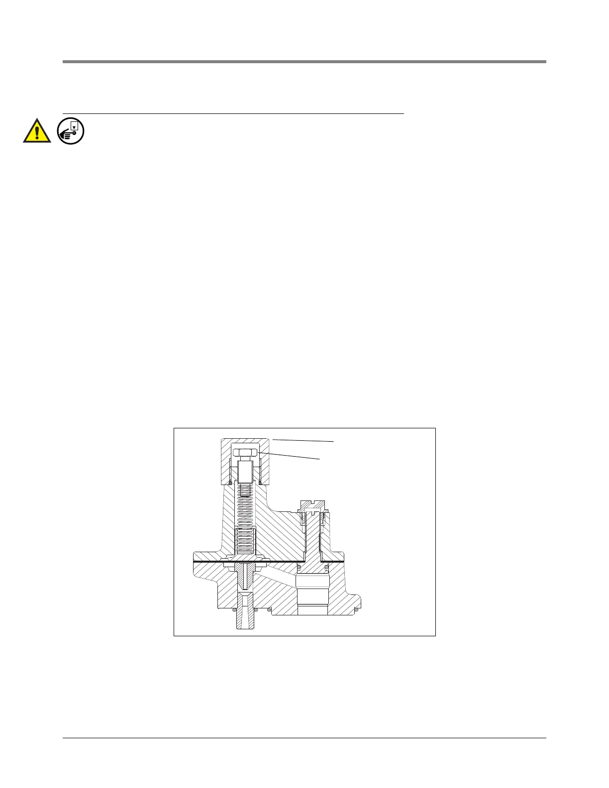
The Functional Element contained in this package is an adjustable model. All new Functional Elements are factory
set at relief pressures of 11.5 - 16 psi (79 - 93 kPa) but can be adjusted to a maximum of approximately 30 psi
(207 kPa) by turning down the adjustment screw.
This adjustment feature allows the use of the Red Jacket Standard pump with electronic line leak detection
systems that require higher relief pressures and enhances performance of electronic line leak detection systems
where field conditions have necessitated minor adjustments to the relief pressure.
To Adjust the Relief Pressure
1. Remove the cap (see Figure 24).
2. Turn down the adjustment screw (see Figure 24). Tightening the screw clockwise will increase the pressure.
When the adjusting screw is fully down, the relief pressure is approximately 30 psi (207 kPa). Fully up will
result in relief pressures between 0 - 3 psi (0 - 20 kPa).
3. Lubricate the cap’s o-ring with petroleum jelly and replace cap by turning it until it contacts the Functional
Element body. Hand tightening is sufficient as the o-ring completes the seal.
There are two methods to verify the relief pressure setting:
a.The pressure reading can be taken from the control unit of an electronic line leak detection system if one is
in operation. Observe the pressure that occurs after the pump turns off - this is the adjusted relief pressure.
b.Pressure may be observed using a gauge attached at the impact valve or the line test port at the pump.
Observe the pressure that occurs after the pump turns off - this the adjusted relief pressure.
Figure 24. Functional element cap and adjustment screw
NOTICE: When the adjustable Functional Element is installed, the pump/motor unit must operate at a minimum of
5 psi (34 kPa) greater than the relief (seating) pressure at which the Functional Element has been set. An improper
pressure setting may cause mechanical damage and will void the warranty.
CAP
ADJUSTMENT SCREW
fig20.eps