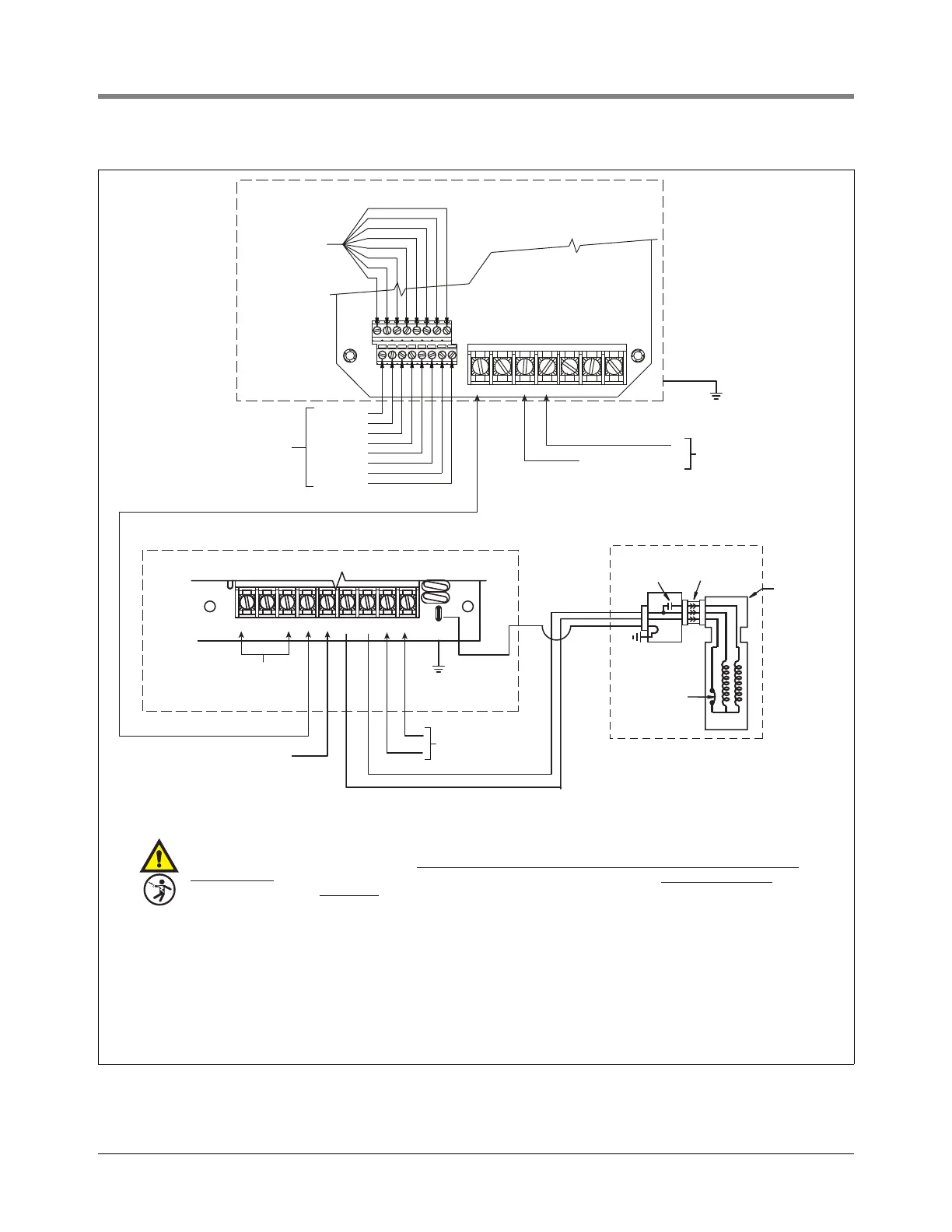
Figure 19. Isotrol to IQ System Wiring - 120 Volt Dispenser Signals
COM+
C23
TB1
D2COM- SHLD D1 M2 L1M1 L2
GND
Z2
Z3
IQ CONTROL BOX (P/N 880-051-1)
ISOTROL CONTROL BOX (P/N 880-049-1)
NEUTRAL
(FROM SUPPLY PANEL)
208/230 VOLT
FROM SUPPLY
PANEL
CHANNEL 1
CHANNEL 2
CHANNEL 3
CHANNEL 4
CHANNEL 5
CHANNEL 6
CHANNEL 7
CHANNEL 8
120 VOLT
DISPENSER
SIGNALS
UNSWITCHED
NEUTRAL TO TB2
TB1
L1
UNSWITCHED NEUTRAL
NOT
USED
NOT
USED
NOT
USED
NOT
USED
1
2
3 456 78
DISPENSER INPUTS
PHASE ON L1 MUST BE SAME AS DEVICE
CONNECTED TO ATG TERMINAL
HOT
NEUTRAL
TB2
AT G
NL1L2M2M1S
RS-485 CONNECTIONS
INSTALL IN CONDUIT
(MANIFOLDED UNITS
ONLY)
CONNECT TO
ELECTRICAL
GROUND
CONNECT TO
ELECTRICAL GROUND
120 V FROM
SUPPLY PANEL
120 VOLT ISOLATED OUTPUT TO IQ CONTROL BOX
153-8.eps
ISOTROL CONTROL BOX WIRING PRECAUTIONS
WARNING! This device is intended to provide electrical isolation between the dispenser pump enable (Hook) signal and the
submersible turbine pump (STP) control relay. Other energized sources of power can still exist within the dispenser even
with this device. The neutral connection to the N terminal of TB1 and N terminal of TB2 must be from the service panel and be
a permanently connected, unswitched connection.
The N connection on TB1 and the eight N connections on TB2 may b
e spliced to a common neutral wire from the service panel
described above.
Make only one "wire" connection on each N terminal on TB2.
CAUTION! The phase of L1 (TB1) must match the phase of the power supplying the ATG device in order to prevent cross phasing
which may damage the input on some ATG equipment.
GENERAL WIRING PRECAUTIONS
Wiring must be rated 90°C minimum.
Make ground connection in accordance with local codes.
Electrical
interlock
Internal
overload
protector
Continuous
duty capacitor
Extractable
packer
Junction box
in manifold
Motor
STP
R
B
O
G